Products: antares
Table of Contents
- 1. Labelling
- 2. Using the wheelchair
- 3. Warnings to reduce any risks associated with misuse of the wheelchair
- 4. Product presentation
- 5. Preparation for use
- 6. Accessories
- 7. Maintenance, inspections and controls
- 8. Cleaning instruction
- 9. Technical service
- 10. Warranty terms
- 11. Packaging, shipment and delivery
- 12. Correct disposal and recycling
- 13. Adjustments
- 13.1. Rear wheel depth adjustment
- 13.2. Adjusting the backrest inclination
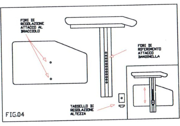
- 13.3. Adjusting the height of the armrests
- 13.4. Front seat height adjustment
- 13.5. Front fork support plate perpendicularity adjustment
- 13.6. Brakes adjustment
- 13.7. Backrest tension adjustment
- 13.8. Backrest height adjustment, pushing handles adjustment
- 13.9. Height adjustable pushing handles adjustment
- 13.10. Footrest height adjustment
- 13.11. Footplate tilt adjustment
- 13.12. Plastic footplates
- 13.13. Pushrim with rivets
- 13.14. Pushrim with splices
- 13.15. Table installation
- 13.16. Abductor assembly
- 13.17. Assembly and adjustment of swing-away lateral supports
Thanks for choosing an OFFCARR product.
OFFCARR listens and responds to the customers' needs by engineering highly technical, innovative solutions aimed at reducing daily mobility problems, with special attention to product style and to improving quality of life.
OFFCARR has a certified system for quality management following UNI EN ISO 9001 regulations and a Medical Device - Quality management system following UNI EN ISO 13485 regulations.
OFFCARR products comply with the european medical device regulation UE MDR 2017/745.

|
Before using or making adjustments on this device, read this instruction manual carefully. |
|
|
Different versions of this manual, accessible for various types of visual disabilities are available on www.offcarr.com |
Contact an authorized dealer or the manufacturer at the following address if clarification regarding the safety measures is required.
|
OFFCARR srl |

|
MADE IN ITALY |

|
Distributor: |
|
|


1. Labelling
Each OFFCARR product is identified by a unique serial number. The serial number, along with other information is visible on the product sticker applied to the frame.
|
Stickers position on the product frame |

Product sticker (applied on the frame) |
|
UDI sticker (applied on the frame and on the instructions for use) |
|


Information available from the product sticker: |
|
|
|
|
Please read all instructions before using the wheelchair. Read all Cautions and Warnings carefully. |
|
European Conformity - This symbol denotes conformity to European standards. |
|
WARNING: Read carefully and follow the indications. |
|
NOTE: Auxiliary information. |
|
Medical Device |
|
UDI: Unique Device Identifier |
|
Serial Number |
|
Reference - This symbol indicates the model of the product. |
|
This symbol indicates the origin country of the product. |
|
The symbol indicates the distributor of the product. |
|
The symbol indicates the manufacturer of the product. |
|
The symbol indicates the maximum load permissible for the product. |
|
The symbol denotes the fixing points for crash tested models. |
|
The symbol denotes the importance of protecting the packaging and the product from harsh weather. |
|
The symbol denotes that shipment must be performed with care and the package must always be kept and stored with the arrows pointing upwards. |


2. Using the wheelchair
|
|
In order to move safely and properly use the wheelchair, it is always recommended to consult qualified personnel. |
Hereafter are some suggestions for a correct use of the wheelchair, also aimed to maintain the characteristics of safety and durability over time:
-
The brakes have only a parking purpose and should never be used as service brakes to slow down the wheelchair in motion.
-
To ensure the efficiency of the brakes, maintain the tyres properly inflated and check quarterly the knurled locking pin wear.
-
The armrests are not designed to lift the wheelchair.
-
Never use anti-tip wheels as transit wheels.
-
Do not lean too far forward, because by moving the centre of gravity, the wheelchair could tip-over.
-
Always deal with slopes above 6° assisted by an attendant. This limit is only approximate and it depends from the specific configuration of the wheelchair, especially the centre of gravity position of the user+wheelchair combination.
-
The wheelchair should be used only for the transport of a person and not of objects in general.
-
Avoid wheeling the wheelchair without the supervision of an attendant.
-
Prolonged contact of the wheelchair with water can cause unwanted oxidation of some metal parts and decay of the security features of the materials involved.
-
Avoid contact with seawater and sand. In case of contact proceed to an immediate and accurate cleaning.
-
Perform a general check of the wheelchair at least every three months, in particular by checking tyre inflation, efficiency of the quick-release axles and brakes and lubricate, if necessary, the moving parts.
-
Clean the wheelchair periodically using a damp cloth and avoid even partial immersion of the frame. Keeping the wheelchair clean enhances its efficiency and as well as helping to enhance its user’s image.
-
Suspend the use of the product and notify OFFCARR in case of allergic reactions or if other similar problems are developed after contact with the device materials.
-
If needed, the upholstery can be washed with water at low temperature. Avoid wetting or submerging any other part of the wheelchair.
-
There is no evidence of danger of injury during the opening and folding operations, when following the instructions written on this manual.
|
|
Make sure the tyres are correctly inflated. Since the correct pressure differs between models, read the required pressure on the side of the tyre itself. |
|
|
Keep the wheelchair away from heat sources, as not all the components are fireproof. |

|
Upholstery materials comply with the ISO 7176-16:2012 regulation. |
|
|
The approximate lifespan of the device is 7 years, considering correct, normal daily use by a single user and frequent maintenance. |
3. Warnings to reduce any risks associated with misuse of the wheelchair
|
|
It is forbidden to use the wheelchairs or parts of them in different ways from those described on this manual. |
|
|
Do not use the brakes to slow down the speed of the wheelchair. They are designed only as parking devices. |
|
|
Do not use the armrests to pick the wheelchair up or as clamping spots. |
|
|
Never use the anti-tip devices, if available, as transit wheels. It is not their intended purpose. |
|
|
It is suggested to verify the proper assembly and the efficiency of the quick-release axle before using the wheelchair, especially if the wheels are removed often. |
|
|
The gap between wheels and side-guards or brakes could be lower than 25 mm. Be careful not to put your fingers between the wheels and side-guards or brakes to avoid injury. |
|
|
To maintain the wheelchair in working order and maintain its safety requirements it is suggested to perform a maintenance program regularly. |
|
|
Poor maintenance and improper use of the device can cause damage or injury to the user or assistant. |
|
|
Any tampering with the components of the wheelchair could compromise the minimum safety requirements . |
|
|
With pneumatic tyres, it is recommended to reduce their pressure in the case of air transport, to avoid collateral effects of pressure variations due to altitude. |
|
|
Contact OFFCARR in case the maximum user weight is exceeded at any point during the wheelchair’s lifespan. |
|
|
Contact OFFCARR or your reseller to check for compatibility with wheelchair accessories produced by a manufacturer different from OFFCARR. |
|
|
The wheelchair and its accessories are not suitable for use in hyperbaric chambers under any circumstances. |
|
|
Before to transferring to or from the wheelchair, activate both parking brakes. Always perform transfers with caution. |
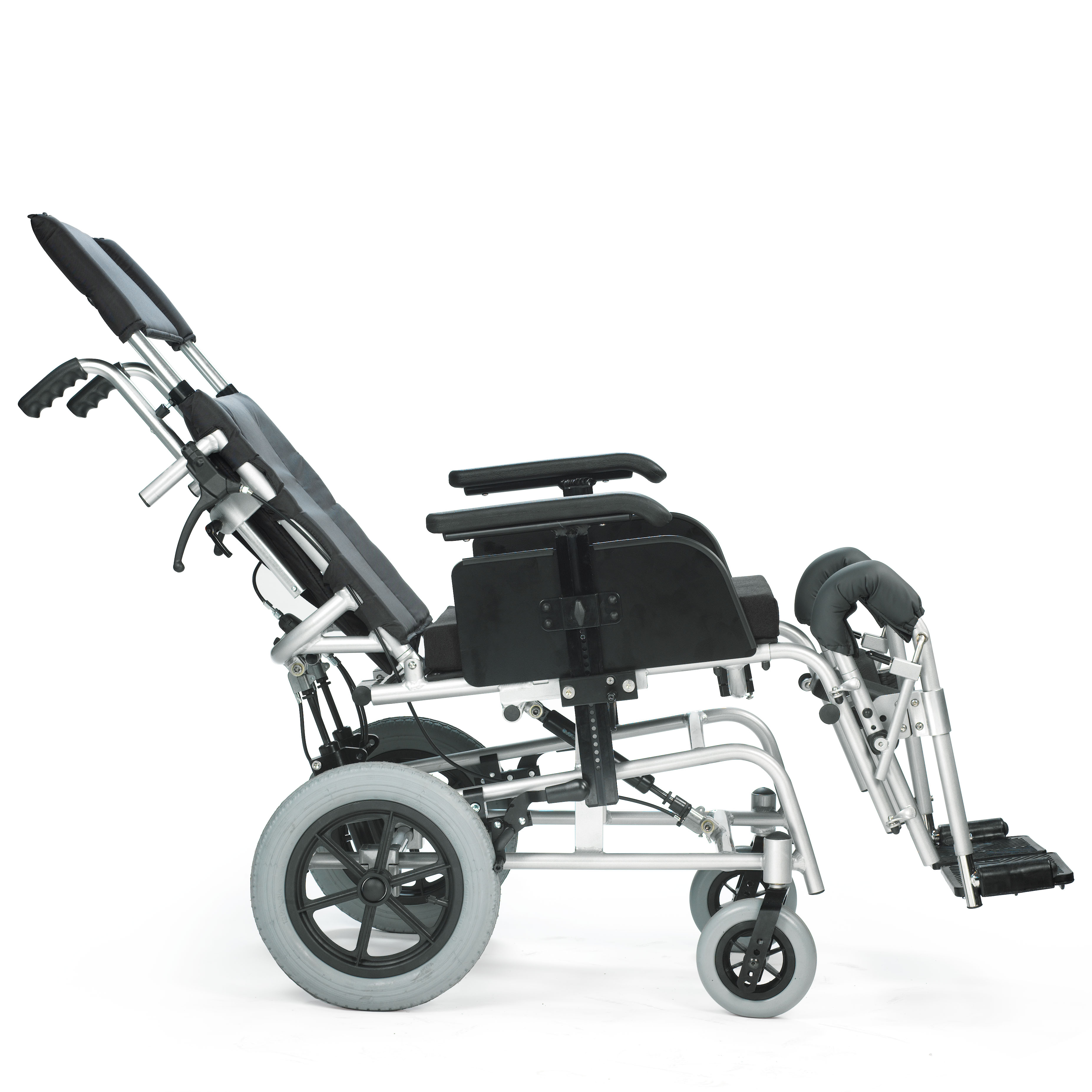
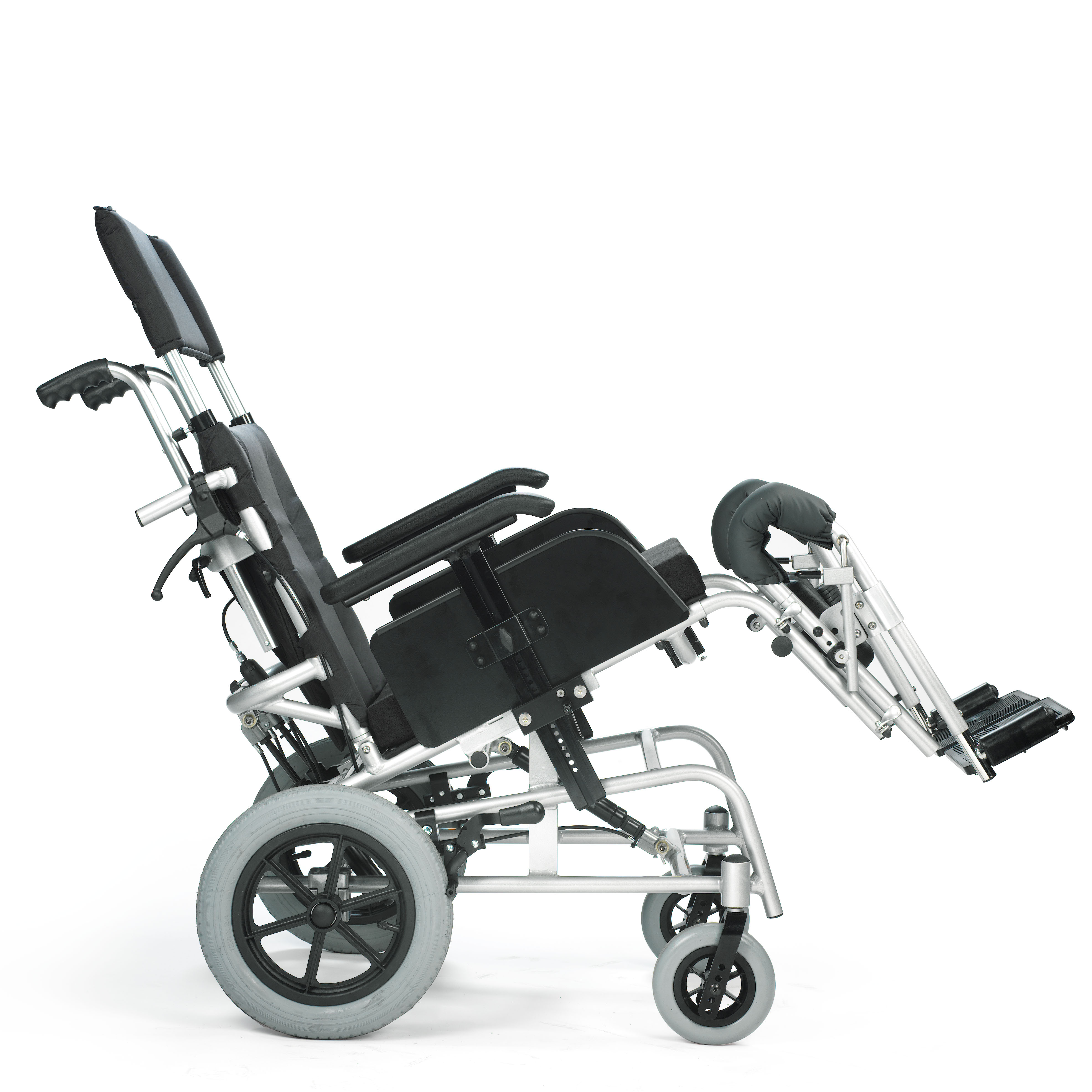
4. Product presentation
4.1. ANTARES
ANTARES is a non invasive medical device, specifically designed to reduce and counterbalance a physical handicap.
ANTARES are non-invasive medical devices specifically designed to reduce and counterbalance motor impairments in the medium and long-term.
This wheelchair is manually propelled on the back wheels, it allows for many configurations and a wide range of accessories to meet the needs of users.
Only qualified operators must setup the device.
|
|
It is forbidden to use the device or its parts in different ways from those described in this manual. |
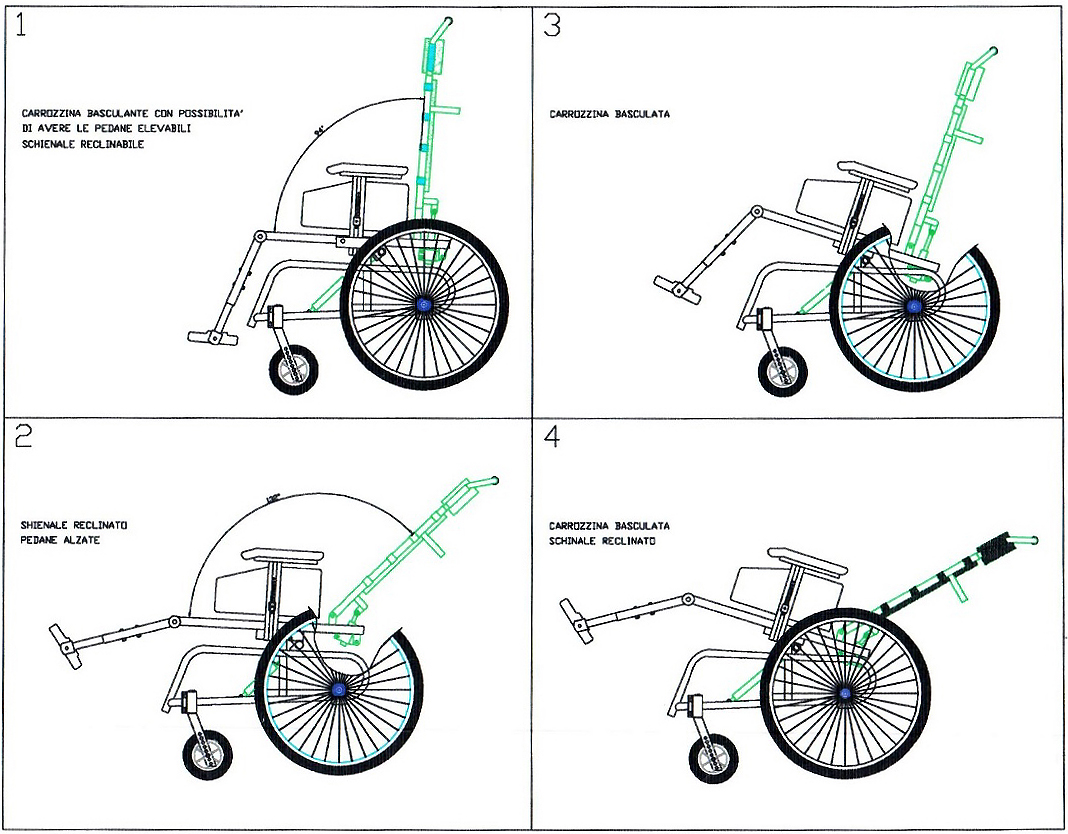
4.1.1. Description
|
|

|
|
Examples of configurations that can be achieved using the ANTARES tilting mechanism |
|
4.1.2. ANTARES Features
ANTARES is an aluminium frame wheelchair, equipped with a tilting system which is generally suitable for non-self-sufficient persons who need to be able to change the seating position. On request, the wheelchair can be supplied with a reclining backrest and elevating seat pad.
-
Light wheelchair
-
Rigid aluminium frame
-
Reclining backrest with gas pistons (also available with fixed positions)
-
Multiple positions for rear wheels
-
Tilt adjustable front fork support
-
Wide range of colours and accessories
-
Black coated nylon upholstery
-
Backrest height adjustment
-
Height-adjustable armrests
-
Fixed or detachable footrests or elevating and detachable
-
Quick extraction of rear wheels
-
Maximum load: 120 kg
See the order form for possible configurations and the full range of options and accessories.
4.1.3. Rear wheel and pushrim diameter
The table indicates diameter of rear wheels and relative pushrims.
| Rear wheel diameter | Pushrim outer diameter (average) |
|---|---|
12" (300 mm) |
Without pushrim |
20" |
445 mm |
22" |
480 mm |
24" |
535 mm |
4.1.4. Front wheel diameter
| Front wheel options | |
|---|---|
125 mm |
solid |
150 mm |
solid |
175 mm |
solid or pneumatic |
5. Preparation for use
|
|
The preparation for use of these devices must be performed by qualified personnel to ensure the specific suitability of the product for the user and the correct working order of all parts and accessories, as well as to provide clear instructions to the user. |
ANTARES is shipped with the rear wheels separated from the frame, the backrest down, the armrests removed and, if present, the headrest disengaged from the backrest.
-
Rotate the backrest backwards by pulling the mushroom behind the seat until the locking pin behind the seat has engaged in its slot on the frame.
-
To assemble the rear wheels to the frame, insert the shaft into the axle bush located under the seat, hold the button down and then release it.
-
Check that the rear wheels engage correctly by checking the button protrudes on the shaft and pulling the wheel outwards without pressing the button.
-
Insert the armrests in the appropriate guides
-
If fitted, position the headrest in the appropriate supports on the backrest, ensuring that the pins lock it into the attachment holes on the backrest tubes.
-
Check the position of the rear wheels and if necessary adjust the wheel axle to find the correct centre of gravity to prevent tipping.
|
|
It is important that preparation for the use of these aids is carried out by qualified personnel both to assess their suitability and to provide the correct instructions for use to the user. |
5.1. Rear wheels release and re-engagement check
|
|
Verify proper operation of the quick-release axle devices before using the wheelchair. |
The wheelchair is usually shipped with the rear wheels disassembled.
|
|

|
|
For safety reasons it is important to repeat this test every time that for transport or maintenance reasons, the rear wheels are removed and reassembled to the frame. |
5.2. Tyre pressure check
Checking the tyre pressure periodically helps maintain the wheelchair efficient and more comfortable.
Verify the tyre pressure value according to the value printed on the tyre sidewall. Indicatively the maximum pressure for the most common models is:
-
7.5 bar (750 kPa - 110 psi) for high pressure rear wheels
-
4.5 bar (450 kPa - 65 psi) for 20", 22", 24" wheels
-
2.5 bar (250 kPa - 30 psi) for pneumatic castor wheels
|
|
With pneumatic tyres, it is recommended to reduce their pressure in the case of air transport, to avoid collateral effects of pressure variations due to altitude. |
5.3. Brakes check
To check the correct functioning and the efficiency of the parking brakes:
-
activate the brakes (ON position)
-
check if the wheels are locked in place
|
|
Pushing brake ON position |
Pushing brake OFF position |


|
|
Drum brake ON position |
Drum brake OFF position |


|
|
Brake type availability is limited depending on the chosen configuration. Not all brake types are available for every setup. |
|
|
The included brakes, except for the assistant-activated brakes (drum), must be used exclusively as parking brakes and never as service brakes. |
|
|
To ensure the efficiency of the brakes it is necessary to maintain the proper tyre pressure and check the wear of the clamping elements frequently. |
5.4. Accessories check
Some accessories required when setting up the wheelchair may be supplied separately. You must assemble them and check their operation before you start using the wheelchair.
6. Accessories
ANTARES can be configured with different accessories, described in the following paragraphs.
6.1. Elevating footrest
Removable and elevating footplates are available for the various ANTARES versions.
|
|
For safety reasons, the elevating footplate must only be operated by the attendant. |
|
|
For safety reasons, the operation to return the footplate from elevated to rest must be carried out by the attendant by simultaneously operating the movement activation lever A with one hand and with the other hand accompanying the descent of the footplate. |
|
|


|
|
The footrest can be elevated to create a continuous plane with the seat: this position is unnatural for a user, so only use it if actually necessary. |
|
|
Elevating footrests are always removable and when inserted increase the overall length of the frame. |
6.2. Table
The choice of a table requires the presence of armrests in the wheelchair configuration.
The tables, which all have cutouts, are available in different materials and sizes:
Plastic (grey): |
one size, 600 mm width |
Soft padded: |
S size, 500 mm width M size, 600 mm width L size, 700 mm width |
Transparent polycarbonate table: |
S size, 500 mm width M size, 600 mm width L size, 700 mm width |
|
|
The connections between table and armrest vary depending on the model of the table itself, and the type of armrests. |
|
|
For each type of table, both central single and double attachments are available. The single attachment is not recommended in the presence of height-adjustable armrests. |
|
|
When ordering any spare parts, it is necessary to specify the serial number of the wheelchair you wish to work on, or provide the wheelchair model, and the type of armrests, elbow-rest and table used. |
Table support
|
Table support with single centre attachment
|
Polycarbonate table with double attachment
|
Polycarbonate or plastic table with double attachment
|


6.3. Swing away lateral supports
ANTARES can be equipped with swing-away lateral supports.
The clamp that attaches to the backrest tube can be rotated to adjust lateral position and angle of containment. The padded support can also be independently adjusted in depth.
The padded supports are available in 4 sizes.
To unlock and open the support, simply lift it vertically by 10mm and rotate it outwards. To activate, turn the holder towards the user until it snaps into the lock when the preset position is reached. |
|

6.4. Backrest extension
Two backrest extension versions are available: fixed and adjustable. The height of the backrest extension and its distance from the end of the backrest are defined when ordering; if the adjustable version is chosen, the distance between the two elements can also be varied over time.
|
Adjusting the backrest extension:
|

6.5. Headrest
Different kind of headrest are available:
Shaped foam headrest |
Form-fitting headrest |
Lateral supports headrest |
|
|
|


|
Adjustment of universal headrest attachment:
|

All headrests can be removed from the wheelchair by pulling them upwards.
It is possible to equip the support with a locking mechanism, this works exactly like the quick-release axle. To release it, press the button (or buttons in case of a double lock) before pulling the whole support upwards.
6.6. Spokes guards
Spokes guards on the rear wheels serve as an esthetic feature as well as protection against accidental insertion of the user’s fingers or hands between the spokes of the wheels. They can be attached to the spokes with velcro or clips depending on the specific model.
|

7. Maintenance, inspections and controls
Weekly:
-
✓ Check the tyre pressure. Each tyre shows on the lateral bands the maximum pressure for which they are designed. A flat tyre affects the efficiency of brakes and the agility of the wheelchair.
-
✓ Check the efficiency of the quick-release axle (see 5.1, “Rear wheels release and re-engagement check”) and if necessary proceed with the lubrication of axle and bushes.
-
✓ Check the tension of the backrest upholstery to maintain a comfortable position.
Quarterly:
-
✓ Check the tightness of all the devices' screws.
-
✓ Check the perpendicularity of the front fork support screws.
-
✓ Check the wear of the front wheels. Solid wheels might be worn to the point of affecting the overall wheelchair front setup. In this case adjust the front fork assembly or replace the wheels (see 7.2, “Replacing front wheels”).
-
✓ Check the efficiency of the bearings. Replace any stuck bearings if necessary (see 7.3, “Replacing rear wheel bearings”, 7.4, “Replacing front wheel bearings” and 7.5, “Replacing front fork holder bearings”).
-
✓ Check the efficiency of the brakes and, in case, adjust them. If the knurled pin has to be replaced, consult authorised personnel.
-
✓ Lubricate moving parts such as hinges, bearings and quick-release axles. It is suggested to use silicon oil, which is efficient and doesn’t smear.
|
|
Only choose original parts when purchasing accessories or spare parts. Contact OFFCARR if you can’t find original spare parts on the market elsewhere. |
|
|
It is recommended to refer only to authorized and qualified personnel to perform maintenance programs, adjustments, and to replace components or accessories. |
7.1. Replacement of tyre and inner tube
7.1.1. Removing the tyre and inner tube
|
|
|
|
|
|
|
|


7.1.2. Assembling the inner tube and tyre
|
|

7.2. Replacing front wheels
If necessary, the front wheels can be replaced:
|
|

|
|
It is important to select the same position for both wheels. Asymmetrical positions produce instability. |
|
|
Once the front wheel has been changed, it is essential to check or adjust the fork perpendicularity to the ground. |
7.3. Replacing rear wheel bearings
Disassembly
|

|
Assembly
|
7.4. Replacing front wheel bearings
Disassembly
|

|
Assembly
|
7.5. Replacing front fork holder bearings
Disassembly
|

|
Assembly
|
7.6. Quick extraction devices
7.6.1. Check
The quick extraction axles are shipped already checked and adjusted. However, it is recommended to periodically verify the effectiveness of their operation.
|
|
7.6.2. Adjustment
If necessary, it is possible to adjust the axle to eliminate any play between the wheel and the frame or to complete the release of the button once the wheel is inserted. |
|

-
If the quick-release button is not completely relaxed when the wheel is inserted in the frame, it is necessary to extend the useful length of the L axle by partially unscrewing the Y nut.
-
If once the wheel has been inserted into the frame, there is play between the frame and the wheel itself, it is necessary to reduce the useful length of the L axis by partially tightening the Y nut.
|
|
The Y nut thread has a pitch of 1 mm, therefore the unscrewing or screwing of one turn involves the elongation or reduction of 1 mm. In case of adjustment, it is advisable to proceed with successive adjustments of ¼ of a turn at a time. |
8. Cleaning instruction
|
|
Cleaning and disinfection procedure have to be performed exclusively by qualified personnel. |
|
|
Follow the instructions on this manual to perform the cleaning and disinfection procedure. |
|
|
Use appropriate eye/facial protection and protective gloves, during cleaning and disinfection procedure. |
In case of contamination with blood or other body fluids, the device has to be cleaned first and then disinfected as follows:
|
|
Most of the time is convenient and more effective to remove the upholstery from the frame before to proceed with the cleaning and disinfection of either frame or upholstery. |
FRAME
-
Wash the device with lukewarm water and neutral detergent using a damp cloth to remove gross soiling
-
Remove eventual detergent residuals only with lukewarm water
-
Dry the device prior to further processing
-
Visually inspect the cleanliness of the complete device
-
Disinfect the device using 70-90% alcohol
-
Be sure it is completely dry before proceeding with use
UPHOLSTERY
In case of the user remaining the same before and after the cleaning treatment:
-
Wash, rinse, dry and disinfect the upholstery using the same process used for the frame
-
Be sure the upholstery parts are completely dry before reassembling them
In case of different user after the cleaning treatment:
-
The best course of action is to change the upholsteries with a new set
|
|
During the cleaning process the device should be also carefully inspected for damage, oxidation and faults in function. If any damage or faults are found, the involved components should be removed for service, repair or replacement. |
|
|
All waste materials related to this process must be disposed in compliance with specific local applicable law. |
9. Technical service
For any service request, please contact OFFCARR supplying the following indications:
-
Model
-
Serial number
-
Fault description
-
Any reference or order number, if available, recorded on the order form.
-
Dealer
Every component of the device is available as spare part.
10. Warranty terms
It is strongly advised to register the product on the website www.offcarr.com after delivery.
-
The device’s frame is guaranteed for 3 (three) years from the delivery date.
-
The label showing the serial number, the manufacturer address and the CE symbol cannot be removed for any reason to preserve the warranty validity.
-
Parts subject to normal wear and tear are not covered by the warranty, unless specific wear is caused by evident manufacturing fault.
-
During the warranty period OFFCARR may proceed at its own discretion to change or to repair the faulty parts.
-
The warranty does not cover damage due to negligence, carelessness, misuse or by incorrect maintenance performed by non authorized personnel.
-
If any damage occurred during transport, the forwarder company is the only responsible. It is important to inform immediately both the forwarder company and, for information, OFFCARR.
-
The warranty does not cover injury or any other damage to people or goods connected to the device’s malfunctioning.
11. Packaging, shipment and delivery
All OFFCARR products are shipped in closed cardboard cases to protect them from bumps and dust.
The package includes the device configured according with the order form, this Instruction manual and a tool kit.
The device must be transported in trucks that protect it from atmospheric agents, as shown on the packaging box.
Upon receipt, check the box integrity: open the package, remove the device and check it for damages. In case of problems, note your remark on the waybill and immediately notify both the forwarder and, for information, OFFCARR.
Once these checks, mandatory to ensure the validity of the warranty, have been carried out, place again the device in its packing until it is used and store in a cool and dry place (between - 15 and + 50 °C and with a relative humidity lower than 80 %).
Do not place any objects over the packaging box.
The packaging materials follow the European directive 94/62/EC[13].
12. Correct disposal and recycling
OFFCARR products are made of aluminium alloy (Al 7020, Al 6082, Al 2017, Al 6061, Al 5754), titanium, steel, stainless steel, carbon fibre, polyurethane, epoxy resins, other composite materials.
Recycle or disposal of all materials must be in compliance with the local applicable laws.
Contact your dealer in case of doubt or for help when disposing the device.
13. Adjustments
The wheelchair is shipped to the customer in the setup chosen on the order form.
Considering potential setup restrictions it is still possible to perform other adjustment to hone in the wheelchair to the specific user.
|
|
Please refer to authorized and qualified personnel to perform the adjustments described in this manual. |
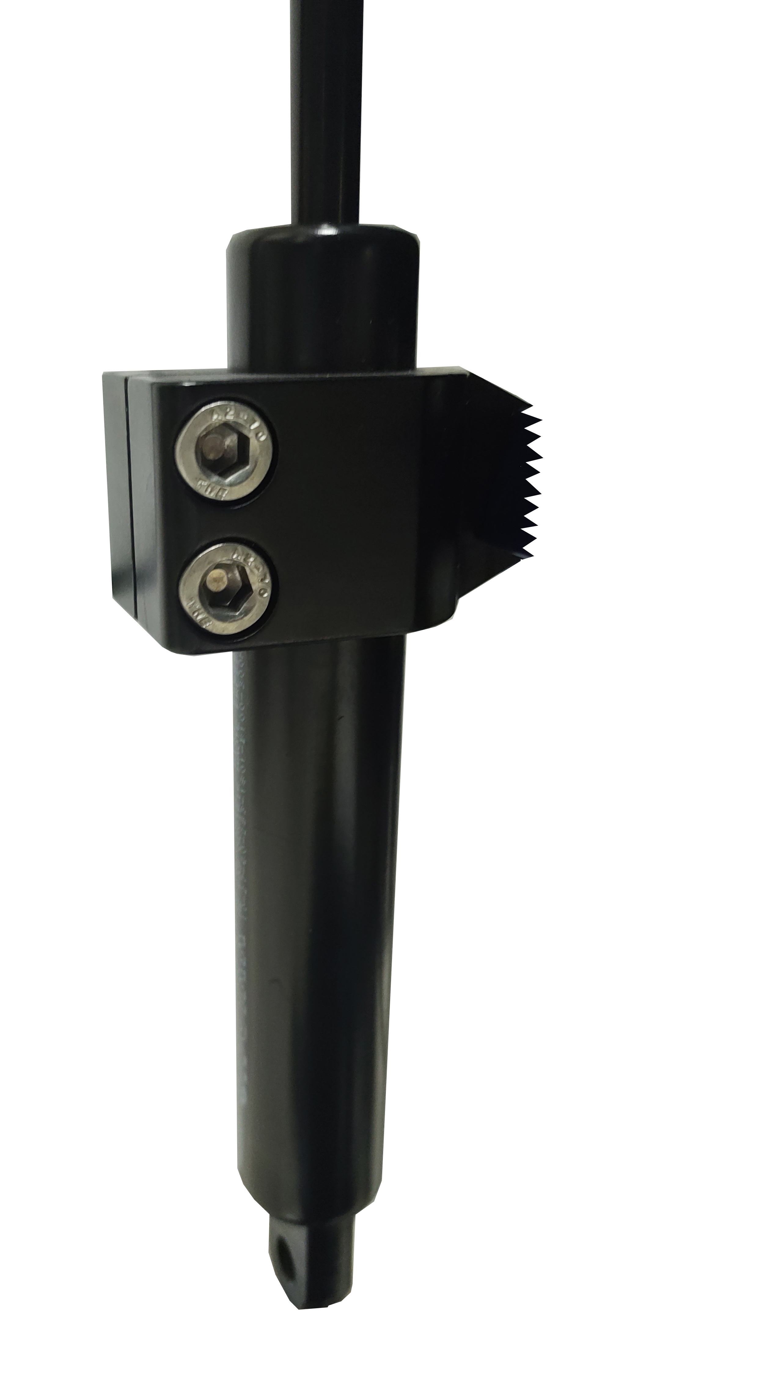
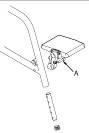
13.1. Rear wheel depth adjustment
-
Remove the wheel by pressing the button located in the shaft in the centre of the rear wheel
-
Unscrew and remove the axle block screws A
-
Advance or retract the axle, moving it parallel to the frame sides
-
Re-tighten and secure the screws A
-
Reinsert the wheels, checking that they engage correctly, making sure that the button does not remain depressed

Note: After adjusting the position of the wheels, adjust the position of the brakes by loosening and then tightening the clamp screws (Fig. 05).
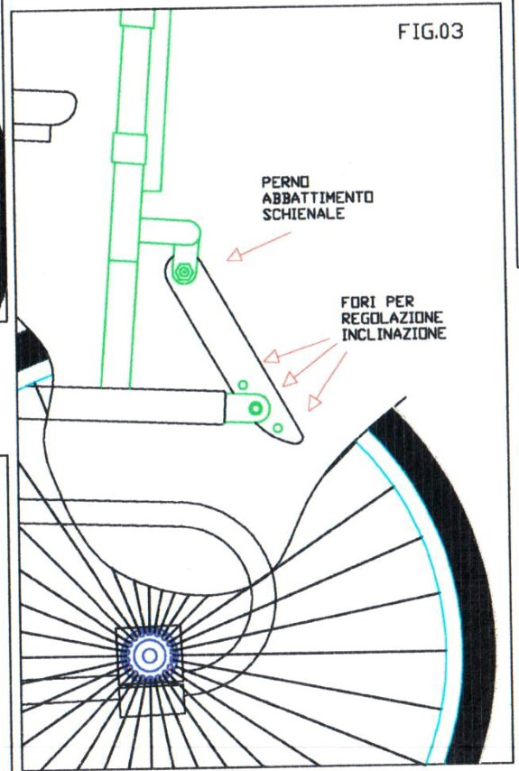
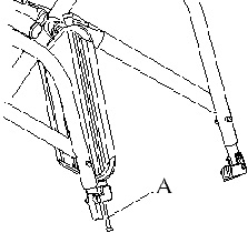
13.2. Adjusting the backrest inclination
In case of gas piston supported backrest:
In case of fixed positions backrest:
|
|
|
13.3. Adjusting the height of the armrests
-
Pull the armrests out
-
Unscrew and remove the locking screws from the sliding blocks
-
Position the dowels at the desired height, with a hole coaxial to the locking thread
-
Re-tighten and secure the locking screws
-
Reinsert the armrests into their sliding seats
|
|
Once changed the front wheels it is essential to adjust the front fork perpendicularity (see 13.5, “Front fork support plate perpendicularity adjustment”). |
13.4. Front seat height adjustment
It is possible to change the front height of the wheelchair by changing the diameter of the front wheels or by choosing a different wheel position on the fork:
|
|

13.5. Front fork support plate perpendicularity adjustment
After making adjustments to the front height or replacing or repositioning the front wheels, the perpendicularity of the front fork plate, i.e. the perpendicularity of the fork pivot axis, must be checked and adjusted if necessary. This adjustment is necessary to achieve maximum steering feel and stability of the wheelchair.
|
|

|
|
Should it prove impossible to achieve perpendicularity, it is advisable to choose the position that generates an angle immediately above 90° (as shown in the figure) in order to keep the wheelchair agile when running and changing direction. |
|
|
The adjustment must be carried out symmetrically on both forks. It is important to check the symmetry carefully after each adjustment. |
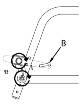
13.6. Brakes adjustment
|
|
With the exception of drum brakes, the brakes provided are only suitable for parking of the aid and not for reducing the running speed. |
If the position of the rear wheel has been changed, the position of the brakes must be adjusted accordingly. Wheelchairs can be equipped with pull, push, scissor or composite brakes.
To adjust the position of the brakes:
CLASSIC BRAKES (pull or push)
|
|

13.7. Backrest tension adjustment
The backrest tension can be easily adjusted by acting on the velcro straps:
|
|
13.8. Backrest height adjustment, pushing handles adjustment
The height of the backrest is chosen when ordering, but further adjustments are possible. The backrest has a telescopic section, regardless from the chosen pushing handles model.
|
|

-
In the presence of side-guards, remove the screws securing them to the frame and take off the corresponding support loop. Adjust the height of the backrest tube and then restore the position and fastening of the side-guards.
|
|
The same procedure can also be followed if the wheelchair has no pushing handles or is configured with height adjustable handles. |
13.9. Height adjustable pushing handles adjustment
If the wheelchair is equipped with height adjustable pushing handles it is possible to adjust them:
|
|

|
|
To change the rest position of the lever B, pull it slightly outwards to release its engagement and rotate it to the new position. |
|
|
The clamp that connects the pushing handle to the wheelchair frame can be rotated around the backrest tube. If necessary, unscrew the safety screw D before turning the screws C to loosen the clamp and allow it to rotate. Once the bracket is secured in its new position, tighten the C screws and then the D safety screw appropriately. |
13.10. Footrest height adjustment
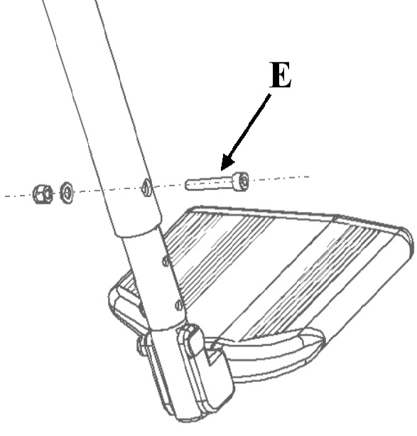
The telescopic footrest support is inserted into the front of the frame and secured through a screw and nut couple E for each side of the frame.
|
|
13.10.1. Seat-to-Footrest Distance Less Than 35cm (ALL)
For a seat-to-footrest distance less than 35cm, the footrest is directly fixed to the frame tube. It’s possible to adjust the footrest height using the provided holes on the frame or to move the footrest closer to or farther from the seat by rotating it around the support. |
|

Changing Footrest Height Using Frame Holes
|
|
Moving the Footrest Closer to or Farther from the Seat
|
|
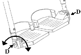
13.11. Footplate tilt adjustment
13.11.1. Single aluminium profile footplate
If the wheelchair is fitted with an aluminium profile single footplate, the orientation of the footplate can be adjusted as follows:
|
|
13.11.2. Separate aluminium footplates
If the wheelchair is fitted with separate aluminium profile footplates, the orientation of the footplates can be adjusted as follows:
|
|

13.12. Plastic footplates
If the wheelchair is fitted with plastic footplates, the orientation of the footplates can be adjusted as follows:
|
|
13.13. Pushrim with rivets
Replacement |
|
|

Adjust the distance between pushrim and rim
|
13.14. Pushrim with splices
Replacement |
|
|

Adjust distance between pushrim and rim |
|
|

13.15. Table installation
To install the table on a wheelchair:
-
Loosen and remove the A screws that connect the elbow-rest to the armrest;
-
Mount the table support paying attention to its direction (right or left) and fix it using two new screws 5 mm longer than the ones removed
-
Put the table supporting tubes in place and fix them to the preferred depth with the B wing screw;
-
Fix the supports to the table with the C screws.
Table support
|
Table support with single centre attachment
|
Polycarbonate table with double attachment
|
Polycarbonate or plastic table with double attachment
|
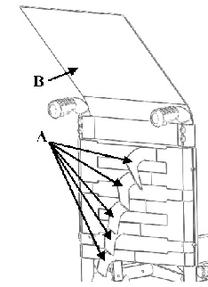
13.16. Abductor assembly
On ANTARES wheelchairs, a pull-out abductor can be fitted.
Follow the instructions below for fitting:
-
Mount the supplied blocks H on the side tubes of the frame
-
Loosen the screws A on the support bar without removing them
-
Assemble the support bar by inserting the lateral ends into the guides of the brackets H, paying attention to the knobs M, and fix the screws A to lock the width
-
Insert the sliding support of the abductor into its guide and secure it with the wing screw N.
To adjust the depth of the abductor, or remove it to facilitate transfers or other manoeuvres of the user in the wheelchair, act as follows:
-
Loosen the wing screw N
-
Position the dock to the desired depth and tighten the wing screw N or completely remove the abductor knob from the seat.
In this case of only removing the abductor knob, the support bar remains mounted on the wheelchair and does not allow it to be closed for transport.
To fold the wheelchair it is essential to remove the abductor knob with the support bar:
-
Pull one of the two knobs M to release the support bar;
-
Remove the support bar by pulling it out of its slots in an arching motion.
The bar can be removed with or without the knob inserted. With the user sitting in the wheelchair, it is recommended to remove the abductor knob separately and then the support bar if necessary.
Support bar
|
Scheme of the abductor parts
|


-
The distance between the seat and the abductor can be reduced by 20 mm by turning the support bar upside down.
-
The sliding support bar is available in various heights, depending on the required distance between the seat canvas and the base of the abductor knob, to suit different cushion options.
13.17. Assembly and adjustment of swing-away lateral supports
Swing-away lateral supports are accessories that can be provided at the time of ordering or can also be fitted later without special arrangements. Their fastening system allows a wide flexibility in finding the preferred positioning while always maintaining the characteristic of openness to facilitate transfers, dressing etc.
It is possible to adjust the height A, the angle between the clamp and the backrest B, the angle of the support C, and the depth position of the soft support D |
|

13.17.1. Height and width support adjustment
|
|

13.17.2. Depth position adjustment:
|
|

OFFCARR s.r.l. reserves the right to make improvements and/or changes on its products, at any time without prior notice, with respect of the device features, suitability, certifications, warranty contract and availability of spare parts according to the terms of law.