Products: top-spin
Table of Contents
- 1. Labelling
- 2. Using the device
- 3. Warnings to reduce any risks associated with misuse of the device
- 4. Product presentation
- 5. Preparation for use
- 6. Manutenzione, ispezioni e controlli
- 7. Cleaning instruction
- 8. Technical service
- 9. Warranty terms
- 10. Packaging, shipment and delivery
- 11. Correct disposal and recycling
- 12. Adjustments
- 12.1. Regolazione dello sbilanciamento (COG)
- 12.2. Regolazione dell’altezza anteriore del sedile da terra
- 12.3. Regolazione dell’altezza posteriore del sedile da terra
- 12.4. Regolazione dell’altezza dello schienale
- 12.5. Regolazione della tensione del telo dello schienale
- 12.6. Regolazione della ruotina antiribaltamento
- 12.7. Regolazione della fascia di fissaggio cosce
- 12.8. Regolazione e sostituzione del corrimano
Thanks for choosing an OFFCARR product.
OFFCARR listens and responds to the customers' needs by engineering highly technical, innovative solutions aimed at reducing daily mobility problems, with special attention to product style and to improving quality of life.
OFFCARR has a certified system for quality management following UNI EN ISO 9001 regulations and a Medical Device - Quality management system following UNI EN ISO 13485 regulations.
OFFCARR products comply with the european medical device regulation UE MDR 2017/745.

|
Before using or making adjustments on this device, read this instruction manual carefully. |
|
|
Different versions of this manual, accessible for various types of visual disabilities are available on www.offcarr.com |
Contact an authorized dealer or the manufacturer at the following address if clarification regarding the safety measures is required.
|
OFFCARR srl |

|
MADE IN ITALY |

|
Distributor: |
|
|


1. Labelling
Each OFFCARR product is identified by a unique serial number. The serial number, along with other information is visible on the product stickers applied to the frame.
|
Stickers position on the product frame |

|
Product sticker (applied on the frame) |
|
UDI sticker (applied on the frame and on the instructions for use) |


Information available on the product sticker: |
|
|
|
1.1. Symbols description
|
Please read all instructions before using the device. Read all Cautions and Warnings carefully. |
|
European Conformity - The symbol denotes conformity to European standards. |
|
WARNING: Read carefully and follow the indications. |
|
NOTE: Auxiliary information. |
|
Medical Device |
|
UDI: Unique Device Identifier |
|
Serial Number |
|
Reference - The symbol indicates the model of the product. |
|
The symbol indicates the country of origin. |
|
The symbol indicates the distributor of the product. |
|
The symbol indicates the manufacturer of the product. |
|
The symbol indicates the maximum load permissible for the product. |
|
The symbol denotes the importance of protecting the packaging and the product from harsh weather. |
|
The symbol denotes that shipment must be performed with care and the package must always be kept and stored with the arrows pointing upwards. |


2. Using the device
|
|
In order to move safely and properly use the device, it is always recommended to consult qualified personnel. |
Hereafter are some suggestions for a correct use of the device, also aimed to maintain the characteristics of safety and durability over time:
-
The brakes only have a parking purpose and should never be used as service brakes to slow down the device in motion.
-
Do not lean too far forward, because by moving the centre of gravity, the device could tip-over.
-
The device should be used only in accordance with what is proposed in this manual and not of objects in general.
-
Always deal with slopes above 6° with assistance from an attendant. This limit is only approximate and it depends on the specific configuration of the device, especially on the position of the centre of gravity of the user-wheelchair combination.
-
To ensure the efficiency of the brakes, maintain the tyres properly inflated and quarterly check the knurled locking pin wear.
-
Never use the anti-tip devices, if available, as transit wheels.
-
The armrests, if available, are not designed to lift the device.
-
Avoid wheeling the device without the supervision of an attendant.
-
Perform a general check of the device at least every three months, by checking tyre inflation, efficiency of the quick-release axles and brakes; lubricate the moving parts whenever necessary.
-
If necessary, the upholstery can be washed with water at low temperature. Avoid wetting or submerging other parts of the device.
-
Prolonged contact of the device with water or prolonged exposure to high humidity levels can cause unwanted oxidation of some metal parts and decay of the security features of the materials involved.
-
Avoid contact with seawater and sand. In case of contact proceed to an immediate and accurate cleaning.
-
Clean periodically the device using a damp cloth and avoid even partial immersion of the frame. Keeping the device clean enhances its efficiency.
|
|
Suspend the use of the product and notify OFFCARR in case of allergic reactions or if other similar problems are developed after contact with the device materials. |
|
|
There is no apparent danger of causing injury to people during the operations of preparation and setup of the device if carried out according to the instructions provided in this manual. |
|
|
Make sure the tyres are correctly inflated. Since the correct pressure differs between models, read the required pressure on the side of the tyre itself. |
|
|
Keep the device away from heat sources, as not all the components are fireproof. |

|
Upholstery materials comply with the EN 1021-2:2014 regulation. |
|
|
The approximate lifespan of the device is 7 years, considering correct, normal daily use by a single user and regular maintenance. |
3. Warnings to reduce any risks associated with misuse of the device
|
|
It is forbidden to use the device or its parts in different ways from those described on this manual. |
|
|
Do not use the brakes, if available, to slow down the device at any speed. They are only designed as parking devices. |
|
|
Do not use the armrests, if available, to pick the device up or as clamping spots. |
|
|
Never use the anti-tip devices, if available, as transit wheels. It is not their intended purpose. |
|
|
It is suggested to frequently check the working order of the quick-release wheel devices, especially after each insertion. |
|
|
The gap between wheels and side-guards or brakes could be lower than 25 mm. Be careful not to put your fingers between the wheels and side-guards or brakes to avoid injury. |
|
|
With pneumatic tyres, it is recommended to reduce their pressure in the case of air transport, to avoid collateral effects of pressure variations due to altitude. |
|
|
To maintain the device efficient and maintain its safety requirements it is recommended to uphold a regular upkeep schedule, as described by this manual. |
|
|
Poor maintenance and improper use of the device can cause damage or injury to the user or assistant. |
|
|
Any tampering with the components of the device, as well as voiding the warranty, could compromise its structural integrity and safety standards. |
|
|
Contact OFFCARR in case the maximum user weight is exceeded at any point during the device’s lifespan. |
|
|
Contact OFFCARR or your reseller to check for compatibility with accessories produced by a manufacturer different from OFFCARR. |
|
|
Do not install on the device mechanical or electronic devices that are not approved by OFFCARR and do not modify its structure in any way. Any combination with other medical devices must be authorized by OFFCARR. In case the combination has been approved, always refer to the respective manuals. |
|
|
The device and its accessories are not suitable for use in hyperbaric chambers under any circumstances. |
|
|
In case of prolonged exposure to the sun, the surface of the device can reach high temperatures. |
|
|
The device is not designed and certified for use as forward-facing seat on a motor vehicle. |
|
|
Before transferring to or from the device, activate the parking brakes. Always perform transfers with caution. |
|
|
Some openings in the device may have angles lower than 75° (e.g. space between wheel spokes) or gaps smaller than 25 mm (e.g. gaps between spokes). |
|
|
For technical and aesthetic reasons the pushing handles may be placed at a height lower than 900 mm from the ground. |
|
|
Headrests (optional) are not approved for use as headrests on moving vehicles. |
|
|
The tip assist pedal and anti-tip devices are optional accessories that must be requested when ordering the device. |
|
|
Do not exceed the weight limit of the devices even temporarily. For example, do not perform activities such as weightlifting on the devices. |
4. Product presentation
4.1. TOP SPIN 3
TOP SPIN 3 è una carrozzina progettata per soddisfare le esigenze di adulti e ragazzi che si avvicinano al gioco del Tennis, praticato su campi da gioco sia indoor che outdoor. Realizzata in lega leggera di alluminio, propone un’ampia gamma di regolazioni per essere configurata secondo le esigenze di atleti con diverse patologie, ed accompagnarli nello sviluppo e nella loro crescita sportiva, ricreativa ed agonistica. Il dispositivo è conforme ai seguenti standard:
-
ISO 7176-8 (con manichino da 120 kg)
-
ISO 7176-16
La configurazione dev’essere eseguita esclusivamente da personale qualificato.
|
|
È vietato l’utilizzo della carrozzina e di sue parti per un uso improprio o diverso da quanto previsto su questo manuale. |
4.1.1. Descrizione
La carrozzina TOP SPIN 3 per il gioco del tennis è caratterizzata da un telaio diviso in due sezioni: un telaio inferiore o base ed un telaio superiore o seduta. La base determina la geometria dell’impronta a terra della carrozzina, l’assetto ed il fissaggio delle ruote grandi di spinta, delle ruotine direzionali anteriori e di quelle antiribaltamento posteriori ed include la pedana e le sue regolazioni.
|
|

4.1.2. Caratteristiche TOP SPIN 3
-
Telaio in lega di alluminio
-
Ruotina centrale antiribaltamento Ø 72 mm regolabile in altezza e profondità
-
Campanatura prestabilita: 18° - 20° - 22°
-
Diametro ruote di trazione: 24" - 25" - 26" - 28”
-
Corrimano in alluminio
-
Ruotine anteriori: piroettanti Ø 72 mm larghezza 23.5 mm
-
Larghezza seduta a scelta: 360, 380, 400, 420 mm
-
Profondità seduta: 380, 400, 420 mm
-
Distanza asse / schienale: da 80 a 210 mm regolabile a step di 10 mm
-
Altezza schienale: 250, 270, 290, 310, 330, 350, 370, 390 mm regolabile
-
Altezza sedile anteriore da terra: da 340 a 540 mm regolabile
-
Altezza sedile post. da terra: da 300 a 540 mm regolabile a step di 10 mm
-
Distanza dall’asse, altezza e inclinazione della pedana: regolabili
-
Cinturino fermapiedi: di serie
-
Portata massima: 120 kg
4.1.3. Tabella delle misure TOP SPIN 3
Le misure sono in gradi (°) e millimetri (mm), il peso è espresso in chilogrammi (kg).
TOP SPIN 3 |
Valori di riferimento |
|
Angolo seduta |
0° ÷ 34° |
|
Angolo schienale |
89° ÷ 92° |
|
Angolo gambe |
130° ÷ 50° |
|
Larghezza totale |
min 790 mm, max 930 mm |
700 |
Lunghezza totale |
min 840 mm, max 890 mm |
1200 |
Altezza totale |
min 570 mm, max 960 mm |
1200 |
Diametro pivot |
min 1580 mm, max 1860 mm |
1300 |
Diametro di sterzata |
min 790 mm, max 930 mm |
1000 |
Peso |
da 11 a 16 kg2 |
Tutte le misure fanno riferimento a carrozzine in assetto standard
L’aggiunta di accessori può modificare le misure indicate
1 Alcune misure possono eccedere i valori di riferimento secondo UNI EN 12183. In alcune circostanze e con determinati assetti l’uso delle uscite di sicurezza potrebbe essere complicato o impossibile
2 Il peso è legato all’assetto selezionato, e può variare in base agli accessori
5. Preparation for use
|
|
The preparation for use of these devices must be performed by qualified personnel to ensure the specific suitability of the product for the user and the correct working order of all parts and accessories, as well as to provide clear instructions to the user. |
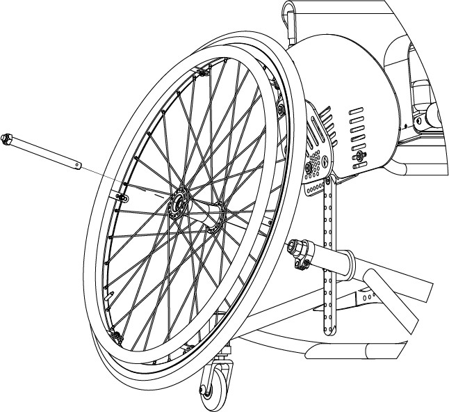
La messa in servizio va eseguita prima di utilizzare il dispositivo e deve essere eseguita dall’utilizzatore o da chi lo assiste. La carrozzina viene spedita con le ruote posteriori smontate, per rimontarle, tenere premuto il pulsante dell’alberino da infilare sulla ruota e successivamente nell’apposita bussola sul telaio della carrozzina e rilasciare il pulsante. Si consiglia di controllare la pressione delle ruote prima dell’uso, normalmente 7,6 bar. La pressione di gonfiaggio è riportata anche sulla spalla delle coperture. Si raccomanda comunque di verificare sempre il corretto inserimento delle ruote di spinta prima di usare la carrozzina controllando il rilascio del pulsante e provando a tirare la ruota verso l’esterno senza premere il pulsante stesso.
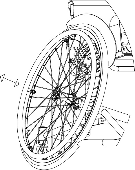
5.1. Verifica estrazione e riaggancio delle ruote posteriori
|
|
Verificare il corretto funzionamento dei dispositivi di aggancio/sgancio rapido delle ruote posteriori prima di utilizzare la carrozzina. |
Normalmente la carrozzina viene spedita con le ruote posteriori sganciate.
|
|
|
|
|
Per ragioni di sicurezza è importante ripetere questo controllo ogni volta che per motivi di trasporto, manutenzione o altro, vengano rimosse e reinserite le ruote posteriori dalla carrozzina. |
5.2. Controllo pressione pneumatici
Controllare periodicamente la pressione degli pneumatici contribuisce a mantenere efficiente la carrozzina e ad offrire maggior comfort di utilizzo.
Verificare il valore della pressione degli pneumatici con il valore indicato sulla copertura.
|
|
In caso di trasporto aereo, si consiglia di diminuire la pressione degli pneumatici al fine di ridurre l’effetto delle variazioni di pressione dovute all’altitudine. |
5.3. Accessories check
Some accessories required when setting up the device may be supplied separately. You must assemble them and check their operation before you start using the device.
6. Manutenzione, ispezioni e controlli
Settimanalmente:
-
✓ Controllare la pressione dei pneumatici. Ogni copertura riporta sulle fasce laterali la pressione per cui sono state progettate. Un pneumatico sgonfio pregiudica e la scorrevolezza della carrozzina.
-
✓ Verificare l’efficienza dei dispositivi di estrazione rapida delle ruote di spinta ( vedi 5.1, “Verifica estrazione e riaggancio delle ruote posteriori” ) e se necessario ungere i perni e le bussole con del lubrificante.
-
✓ Controllare il tensionamento del telo dello schienale per mantenere una posizione confortevole.
Trimestralmente:
-
✓ Controllare il fissaggio delle viti delle piastre porta ruota posteriori.
-
✓ Controllare il fissaggio e la perpendicolarità delle forcelle anteriori.
-
✓ Verificare l’usura delle ruote anteriori. Nel caso di ruotine piene potrebbero essere usurate al punto tale da influire sull’assetto anteriore della carrozzina. In questo caso regolare l’allineamento delle forcelle anteriori o sostituire le ruote (vedi 6.2, “Sostituzione delle ruotine anteriori”).
-
✓ Verificare l’efficienza dei cuscinetti sulle ruote di spinta, sulle ruotine anteriori e sulla rotazione delle relative forcelle. Se necessario procedere alla sostituzione dei cuscinetti (vedi 6.4, “Replacing rear wheel bearings” e 6.3, “Sostituzione dei cuscinetti della ruota anteriore”).
-
✓ Lubrificare le parti in movimento come snodi, alberini e bussole. Come lubrificante suggeriamo un olio siliconico, che è efficiente e non sporca.
|
|
Si raccomanda di usare solo parti di ricambio originali. Contattare OFFCARR in caso di difficoltà di reperimento nel mercato di ricambi ed accessori originali. |
|
|
Si raccomanda di affidarsi esclusivamente a personale esperto ed autorizzato per qualsiasi intervento di manutenzione, regolazione e sostituzione di parti che compongono la carrozzina. |
6.1. Replacement of tyre and inner tube
6.1.1. Removing the tyre and inner tube
|
|
|
|
|
|
|
|


6.1.2. Assembling the inner tube and tyre
|
|

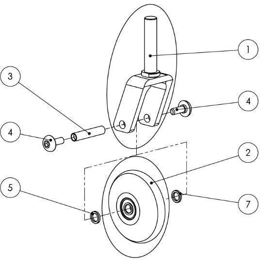
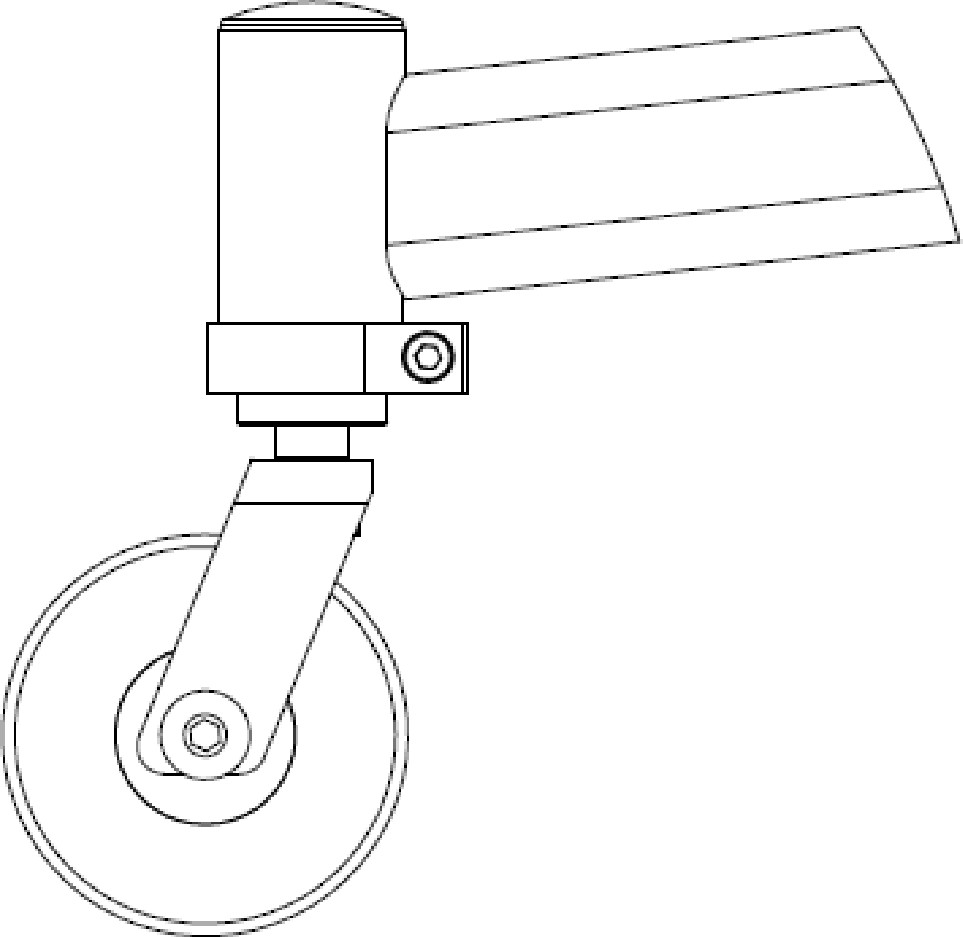
6.2. Sostituzione delle ruotine anteriori
Se necessario le ruotine anteriori possono essere sostituite:
|
|
|
|
È importante selezionare la medesima posizione per entrambe le ruote. Posizioni asimmetriche producono instabilità. |
|
|
Una volta sostituita la ruota anteriore, è essenziale verificare o regolare la perpendicolarità della forcella rispetto al suolo. |
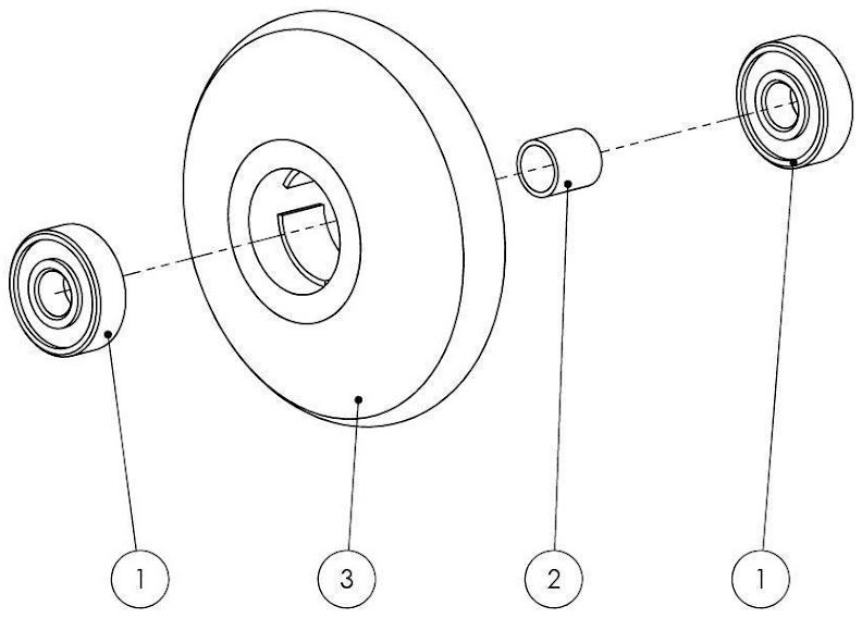
6.3. Sostituzione dei cuscinetti della ruota anteriore
Smontaggio
|
|
6.4. Replacing rear wheel bearings
Disassembly
|

|
Assembly
|
6.5. Quick extraction devices
6.5.1. Check
The quick extraction axles are shipped already checked and adjusted. However, it is recommended to periodically verify the effectiveness of their operation.
|
|

6.5.2. Adjustment
If necessary, it is possible to adjust the axle to eliminate any play between the wheel and the frame or to complete the release of the button once the wheel is inserted. |
|

-
If the quick-release button is not completely relaxed when the wheel is inserted in the frame, it is necessary to extend the useful length of the L axle by partially unscrewing the Y nut.
-
If once the wheel has been inserted into the frame, there is play between the frame and the wheel itself, it is necessary to reduce the useful length of the L axis by partially tightening the Y nut.
|
|
The Y nut thread has a pitch of 1 mm, therefore the unscrewing or screwing of one turn involves the elongation or reduction of 1 mm. In case of adjustment, it is advisable to proceed with successive adjustments of ¼ of a turn at a time. |
7. Cleaning instruction
|
|
Cleaning and disinfection procedure have to be performed exclusively by qualified personnel. |
|
|
Follow the instructions on this manual to perform the cleaning and disinfection procedure. |
|
|
Use appropriate eye/facial protection and protective gloves, during cleaning and disinfection procedure. |
In case of contamination with blood or other body fluids, the device has to be cleaned first and then disinfected as follows:
|
|
Most of the time is convenient and more effective to remove the upholstery from the frame before to proceed with the cleaning and disinfection of either frame or upholstery. |
FRAME
-
Wash the device with lukewarm water and neutral detergent using a damp cloth to remove gross soiling
-
Remove eventual detergent residuals only with lukewarm water
-
Dry the device prior to further processing
-
Visually inspect the cleanliness of the complete device
-
Disinfect the device using 70-90% alcohol
-
Be sure it is completely dry before proceeding with use
UPHOLSTERY
In case of the user remaining the same before and after the cleaning treatment:
-
Wash, rinse, dry and disinfect the upholstery using the same process used for the frame
-
Be sure the upholstery parts are completely dry before reassembling them
In case of different user after the cleaning treatment:
-
The best course of action is to change the upholsteries with a new set
|
|
During the cleaning process the device should be also carefully inspected for damage, oxidation and faults in function. If any damage or faults are found, the involved components should be removed for service, repair or replacement. |
|
|
All waste materials related to this process must be disposed in compliance with specific local applicable law. |
8. Technical service
For any service request, please contact OFFCARR supplying the following indications:
-
Model
-
Serial number
-
Fault description
-
Any reference or order number, if available, recorded on the order form.
-
Dealer
Every component of the device is available as spare part.
9. Warranty terms
It is strongly advised to register the product on the website www.offcarr.com after delivery.
-
The device’s frame is guaranteed for 2 (two) years from the delivery date.
-
The label showing the serial number, the manufacturer address and the CE symbol cannot be removed for any reason to preserve the warranty validity.
-
Parts subject to normal wear and tear are not covered by the warranty, unless specific wear is caused by evident manufacturing fault.
-
During the warranty period OFFCARR may proceed at its own discretion to change or to repair the faulty parts.
-
The warranty does not cover damage due to negligence, carelessness, misuse or by incorrect maintenance performed by non authorized personnel.
-
If any damage occurred during transport, the forwarder company is the only responsible. It is important to inform immediately both the forwarder company and, for information, OFFCARR.
-
The warranty does not cover injury or any other damage to people or goods connected to the device’s malfunctioning.
10. Packaging, shipment and delivery
All OFFCARR products are shipped in closed cardboard cases to protect them from bumps and dust.
The package includes the device configured according with the order form, this Instruction manual and a tool kit.
The device must be transported in trucks that protect it from atmospheric agents, as shown on the packaging box.
Upon receipt, check the box integrity: open the package, remove the device and check it for damages. In case of problems, note your remark on the waybill and immediately notify both the forwarder and, for information, OFFCARR.
Once these checks, mandatory to ensure the validity of the warranty, have been carried out, place again the device in its packing until it is used and store in a cool and dry place (between - 15 and + 50 °C and with a relative humidity lower than 80 %).
Do not place any objects over the packaging box.
The packaging materials follow the European directive 94/62/EC[13].
11. Correct disposal and recycling
OFFCARR products are made of aluminium alloy (Al 7020, Al 6082, Al 2017, Al 6061, Al 5754), titanium, steel, stainless steel, carbon fibre, polyurethane, epoxy resins, other composite materials.
Recycle or disposal of all materials must be in compliance with the local applicable laws.
Contact your dealer in case of doubt or for help when disposing the device.
12. Adjustments
Considering potential setup restrictions it is still possible to perform other adjustment to hone in the wheelchair to the specific user.
|
|
Please refer to authorized and qualified personnel to perform the adjustments described in this manual. |
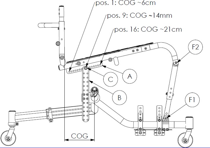
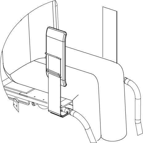
12.1. Regolazione dello sbilanciamento (COG)
Lo sbilanciamento o centro di gravità corrisponde alla distanza orizzontale dello schienale dall’asse delle ruote di trazione. É un parametro determinante per la distribuzione del carico tra le ruote posteriori di trazione e quelle anteriori della carrozzina, influenzando pesantemente l’agilità e la gestione del mezzo. Lo sbilanciamento viene prefissato in base alla scheda d’ordine ma è possibile regolarlo diversamente a step di 10 mm circa:
-
Rimuovere le protezioni imbottite anteriori del telaio.
-
Allentare senza togliere le viti F1 che fissano il montanti frontali alla base del telaio.
-
Allentare senza togliere le viti F2 per liberare la rotazione tra i montanti frontali ed il sedile.
-
Svitare e rimuovere le viti C che fissano il sedile alle barre di sostegno posteriori.
-
Muovere avanti o indietro il sedile fino a trovare la COG desiderata.
-
Rimettere e fissare opportunamente le viti C nella nuova posizione.
-
Se non sono richieste ulteriori modifiche di assetto, fissare opportunamente le viti F1 e F2 allentate in precedenza.
|
|
La scelta del centro di gravità è sempre un compromesso tra l’agilità d’uso e la sicurezza. Con una configurazione molto attiva, la carrozzina risulta molto agile nella spinta ma richiede maggiore abilità nel controllo. Un baricentro più prudente aumenta la stabilità dell’ausilio a scapito della sua agilità. Si tratta di una scelta individuale legata alla configurazione generale del dispositivo, all’anatomia e alla disabilità dell’utente e all’ambiente di utilizzo; una scelta che determina l’esperienza di spinta. L’opportunità di variare nel tempo tale parametro consente al dispositivo di accompagnare l’evoluzione motoria dell’utente ottimizzandone le potenzialità. |
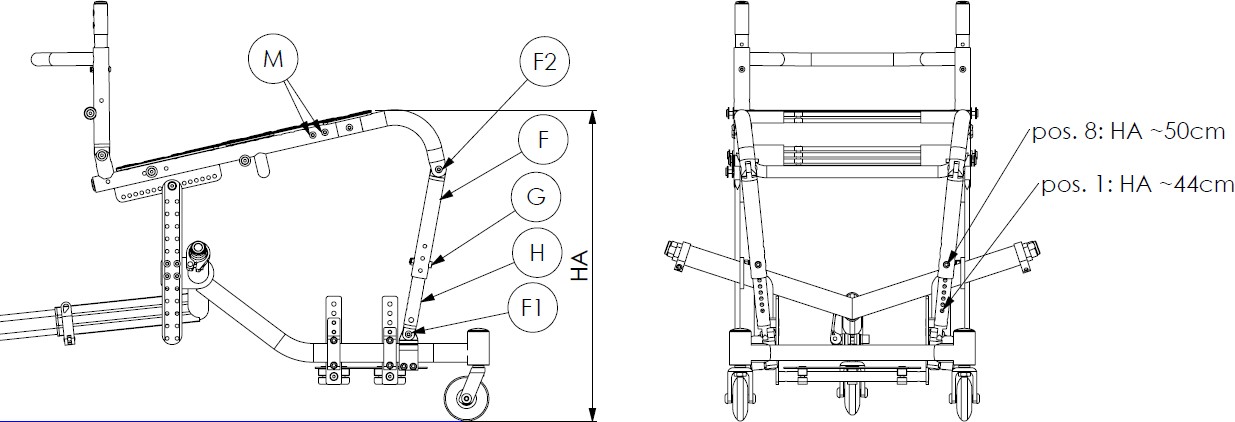
12.2. Regolazione dell’altezza anteriore del sedile da terra
L’altezza anteriore del sedile da terra, è regolabile tra 440 e 540 mm. La carrozzina viene però fornita con un kit a corredo per raggiungere anche le altezze anteriori 420 e 400 mm. Per variare la posizione del montante tra 440 e 540 mm eseguire le indicazioni seguenti:
-
Rimuovere le protezioni imbottite anteriori del telaio.
-
Allentare senza togliere le viti F1 che fissano il montanti frontali alla base del telaio.
-
Allentare senza togliere le viti F2 per liberare la rotazione dei montanti anteriori rispetto al sedile.
-
Svitare e rimuovere le viti G che fissano le sezioni telescopiche anteriori del telaio.
-
Scegliere l’altezza desiderata del sedile da terra misurata tra la fine del sedile e terra (HA).
-
Rimettere e fissare opportunamente le viti G nella nuova posizione.
-
Se non sono richieste ulteriori modifiche di assetto del sedile, fissare opportunamente le viti F1 e F2 allentate in precedenza.
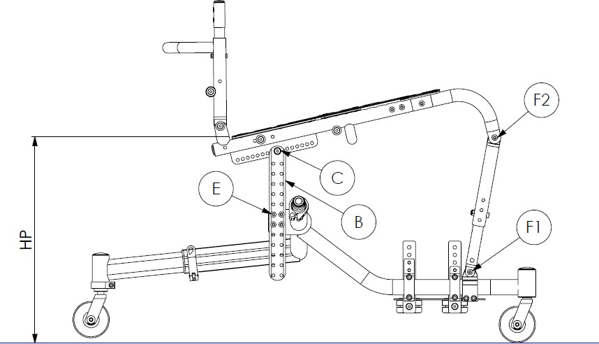
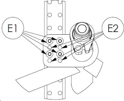
12.3. Regolazione dell’altezza posteriore del sedile da terra
L’altezza posteriore del sedile da terra è regolabile tra 340 e 530 mm eseguendo le indicazioni seguenti:
-
Allentare senza togliere le viti F1, C, F2 per liberare eventuali blocchi di rotazione e movimento del telaio della seduta.
-
Svitare e rimuovere le viti E che fissano le barre di sostegno posteriori.
-
Scegliere l’altezza desiderata del sedile da terra misurata tra la fine posteriore del sedile e terra “HP”.
-
Rimettere le viti E nella nuova posizione e stringerle opportunamente.
-
Se non sono richieste ulteriori modifiche di assetto del sedile, fissare opportunamente le viti F1, C, F2 allentate in precedenza.
|
|
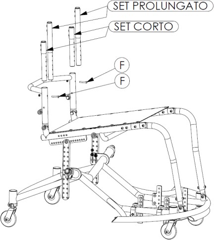
12.4. Regolazione dell’altezza dello schienale
L’altezza dello schienale è regolabile tra 250 e 390 mm eseguendo le indicazioni seguenti:
-
Alzare e togliere il telo dello schienale fissato con le fasce velcrate alle cinghie di sostegno.
-
Svitare le viti F che fissano le prolunghe di regolazione in altezza dello schienale.
-
Scegliere la nuova altezza per lo schienale.
-
Rimettere le viti F nella nuova posizione e stringerle opportunamente.
-
Se necessario aggiungere una o più cinghie velcrate di supporto dell’imbottitura esterna.
-
Rimettere il telo schienale avendo cura di ripiegare sotto il cuscino la sezione eccedente.
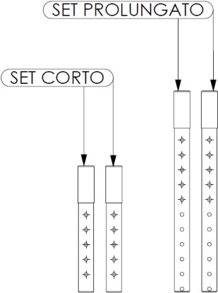
NOTA: La carrozzina dispone di due set di prolunghe schienale. Il set corto, montato nella configurazione di fornitura copre una regolazione in altezza tra 250 e 310 mm. Il set prolungato, fornito in dotazione, copre regolazioni comprese tra 330 e 390 mm. Le cinghie di sostegno fornite coprono l’intera gamma di regolazione, come pure il telino imbottito di copertura.
|
|
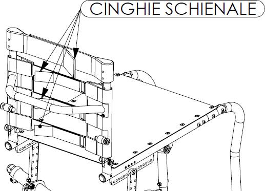
12.5. Regolazione della tensione del telo dello schienale
-
Alzare il telo nella parte posteriore
-
Allentare le cinghie
-
Con l’atleta in posizione di gioco tendere le cinghie quanto basta partendo da quella superiore
-
Ripiegare nuovamente il telo schienale
-
Provare alcuni movimenti di gioco ed eventualmente ripetere l’operazione se la postura non è quella attesa
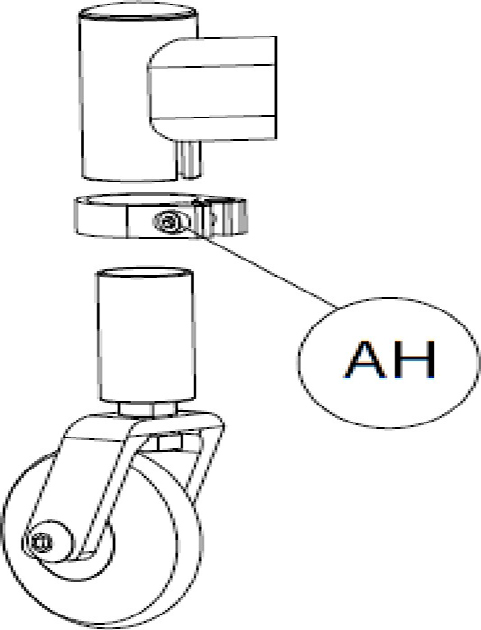
12.6. Regolazione della ruotina antiribaltamento
Per variare l’altezza della ruotina:
-
Allentare senza togliere la vite AH che fissa l’altezza da terra della ruotina antiribaltamento
-
Alzare o abbassare la ruotina secondo le proprie preferenze
-
Stringere opportunamente la vite AH
|
|
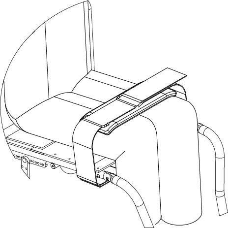
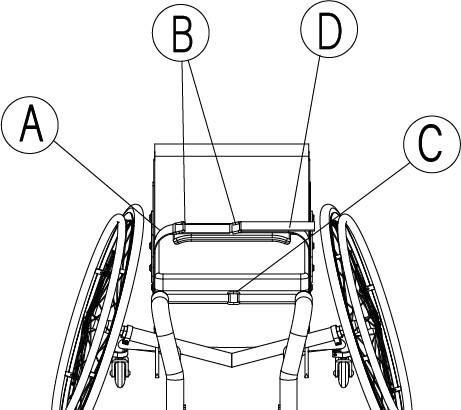
12.7. Regolazione della fascia di fissaggio cosce
12.7.1. Preparazione
La fascia di fissaggio cosce è formata da:
-
una fascia con imbottitura A con 2 fibbie B,
12.7.2. Regolazione
La regolazione della fascia di fissaggio cosce va eseguita con l’atleta seduto sulla carrozzina.
-
Posizionare la fascia A con l’area imbottita centrata sopra le cosce,
-
Inserire la fascia di fissaggio D dentro una delle due fibbie superiori B in base a come si trova meglio l’utente.
-
Se la lunghezza non è idonea è possibile regolarla opportunamente agendo sull’aggiustamento dell’unione delle fasce velcrate A e D che si trova sotto la seduta.
|
|
|
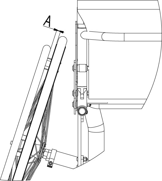
12.8. Regolazione e sostituzione del corrimano
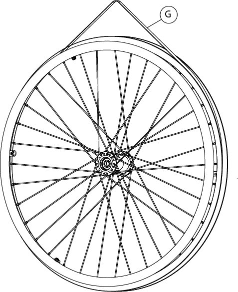
Il corrimano può essere montato in tre posizioni differenti per ottenere una distanza A dal cerchio della ruota più o meno ampia. Per accedere alle viti che fissano il corrimano è necessario rimuovere la copertura, la camera d’aria (vedi 6.1, “Replacement of tyre and inner tube”) ed il flap di protezione G
|
|
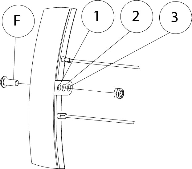
Per smontare il corrimano dalla ruota è necessario rimuovere completamente tutte le sei viti di fissaggio F. Una volta smontato il corrimano, è possibile rimontarlo scegliendo la posizione desiderata tra le tre opzioni presenti sulle alette di fissaggio (vedi illustrazione)
|
|

Una volta rimontato il corrimano procedere con il riposizionamento del flap G ponendo attenzione a far coincidere il foro per la valvola con il relativo foro nel cerchio. Si raccomanda di centrare il flap G sul cerchio per assicurare la massima protezione alla camera d’aria
OFFCARR s.r.l. reserves the right to make improvements and/or changes on its products, at any time without prior notice, with respect of the device features, suitability, certifications, warranty contract and availability of spare parts according to the terms of law.