Table of Contents
- 1. Labelling
- 2. Using the device
- 3. Warnings to reduce any risks associated with misuse of the device
- 4. Product presentation
- 5. Preparation for use
- 6. Maintenance, inspections and controls
- 7. Troubleshooting (STAND-UP ST, STAND-UP EE, STAND-UP ETM)
- 8. Cleaning instruction
- 9. Technical service
- 10. Warranty terms
- 11. Packaging, shipment and delivery
- 12. Correct disposal and recycling
- 13. Adjustments
- 14. Manual activation of the actuator in case of emergency (STAND-UP ST, STAND-UP EE, STAND-UP ETM)
Thanks for choosing an OFFCARR product.
OFFCARR listens and responds to the customers' needs by engineering highly technical, innovative solutions aimed at reducing daily mobility problems, with special attention to product style and to improving quality of life.
OFFCARR has a certified system for quality management following UNI EN ISO 9001 regulations and a Medical Device - Quality management system following UNI EN ISO 13485 regulations.
OFFCARR products comply with the european medical device regulation UE MDR 2017/745.

|
Before using or making adjustments on this device, read this instruction manual carefully. |
|
|
Different versions of this manual, accessible for various types of visual disabilities are available on www.offcarr.com |
Contact an authorized dealer or the manufacturer at the following address if clarification regarding the safety measures is required.
|
OFFCARR srl |

|
MADE IN ITALY |

|
Distributor: |
|
|


1. Labelling
Each OFFCARR product is identified by a unique serial number. The serial number, along with other information is visible on the product stickers applied to the frame.
Stickers position on the frame (HAPPY STANDING) |
|
Stickers position on the frame (STAND-UP ST, STAND-UP EE, STAND-UP ETM) |
|


|
Product sticker (applied on the frame) |
|
UDI sticker (applied on the frame and on the instructions for use) |


Information available on the product sticker: |
|
|
|
1.1. Symbols description
|
Please read all instructions before using the device. Read all Cautions and Warnings carefully. |
|
European Conformity - The symbol denotes conformity to European standards. |
|
WARNING: Read carefully and follow the indications. |
|
NOTE: Auxiliary information. |
|
Medical Device |
|
UDI: Unique Device Identifier |
|
Serial Number |
|
Reference - The symbol indicates the model of the product. |
|
The symbol indicates the country of origin. |
|
The symbol indicates the distributor of the product. |
|
The symbol indicates the manufacturer of the product. |
|
The symbol indicates the maximum load permissible for the product. |
|
The symbol denotes the importance of protecting the packaging and the product from harsh weather. |
|
The symbol denotes that shipment must be performed with care and the package must always be kept and stored with the arrows pointing upwards. |


2. Using the device
|
|
In order to move safely and properly use the device, it is always recommended to consult qualified personnel. |
Hereafter are some suggestions for a correct use of the device, also aimed to maintain the characteristics of safety and durability over time:
-
The brakes only have a parking purpose and should never be used as service brakes to slow down the device in motion.
-
Do not lean too far forward, because by moving the centre of gravity, the device could tip-over.
-
The device should be used only in accordance with what is proposed in this manual and not of objects in general.
-
Always deal with slopes above 6° with assistance from an attendant.
-
Prolonged contact of the device with water or prolonged exposure to high humidity levels can cause unwanted oxidation of some metal parts and decay of the security features of the materials involved.
-
Avoid contact with seawater and sand. In case of contact proceed to an immediate and accurate cleaning.
-
Clean periodically the device using a damp cloth and avoid even partial immersion of the frame. Keeping the device clean enhances its efficiency.
|
|
Suspend the use of the product and notify OFFCARR in case of allergic reactions or if other similar problems are developed after contact with the device materials. |
|
|
There is no apparent danger of causing injury to people during the operations of preparation and setup of the device if carried out according to the instructions provided in this manual. |
|
|
Keep the device away from heat sources, as not all the components are fireproof. |

|
Upholstery materials comply with the EN 1021-2:2014 regulation. |
3. Warnings to reduce any risks associated with misuse of the device
|
|
It is forbidden to use the device or its parts in different ways from those described on this manual. |
|
|
For safety reasons, it is important that all positioning operations of the user on the seat are carried out with the help of an assistant. |
|
|
The device is designed for indoor use. Proceed with caution on other pavement types. |
|
|
Do not use the brakes, if available, to slow down the device at any speed. They are only designed as parking devices. |
|
|
It is suggested to frequently check the working order of the quick-release wheel devices, especially after each insertion. (HAPPY STANDING) |
|
|
With pneumatic tyres, it is recommended to reduce their pressure in the case of air transport, to avoid collateral effects of pressure variations due to altitude. |
|
|
To maintain the device efficient and maintain its safety requirements it is recommended to uphold a regular upkeep schedule, as described by this manual. |
|
|
Poor maintenance and improper use of the device can cause damage or injury to the user or assistant. |
|
|
Any tampering with the components of the device, as well as voiding the warranty, could compromise its structural integrity and safety standards. |
|
|
Contact OFFCARR in case the maximum user weight is exceeded at any point during the device’s lifespan. |
|
|
Contact OFFCARR or your reseller to check for compatibility with accessories produced by a manufacturer different from OFFCARR. |
|
|
Do not install on the device mechanical or electronic devices that are not approved by OFFCARR and do not modify its structure in any way. Any combination with other medical devices must be authorized by OFFCARR. In case the combination has been approved, always refer to the respective manuals. |
|
|
The device and its accessories are not suitable for use in hyperbaric chambers under any circumstances. |
|
|
In case of prolonged exposure to the sun, the surface of the device can reach high temperatures. |
|
|
Before transferring to or from the device, activate the parking brakes. Always perform transfers with caution. |
|
|
Some openings in the device may have angles lower than 75° (e.g. space between wheel spokes) or gaps smaller than 25 mm (e.g. gaps between spokes). |
|
|
Use the device and its parts exclusively for their intended purpose. |
|
|
The device is suitable for use by children and teenagers; however, adult supervision is recommended. |
4. Product presentation
4.1. HAPPY STANDING
HAPPY STANDING is a device designed so that children with lower limb impairment can maintain an upright position with the ability to move independently.
The device is suitable for indoor use, limited by the size of the spaces and the size of the device.
HAPPY STANDING are non-invasive medical devices specifically designed to reduce and counterbalance motor impairments in the medium and long-term.
Only qualified operators must setup the device.
|
|
It is forbidden to use the device or its parts in different ways from those described in this manual. |
4.1.1. Description
|
|

4.1.2. Features
HAPPY STANDING: Standing aid available in smaller measurements, suitable for children.
-
Max user height: 130 cm
-
Fixed steel and aluminium frame
-
Three pushing wheel dimensions: 24", 26" or 28"
-
With pushrim and parking brakes activated also by user
-
Pivoting rear caster with integrated brake activated by attendant
-
Front safety wheels
-
Customizable with abductor, saddle, pelvic support, table or any combination of them
-
Maximum load: 75 kg
4.1.3. Measurements table
All measurements are in degrees (°) and millimetres (mm), the weight is expressed in kilograms (kg).
HAPPY STANDING |
Reference values |
|
Chest support |
adjustable in height |
|
Saddle |
adjustable in height |
|
Pelvic support |
adjustable in depth and height |
|
Calf supports |
adjustable in height, depth, width position |
|
Total width |
600 |
7001 |
Total length |
1000 |
12001 |
Total height |
adjustable |
12001 |
Weight2 |
24.5 kg |
All measurements refer to device in standard configuration
The addition of accessories may modify the indicated measurements and weight
1 Some measurements may exceed the reference values according to UNI EN 12183. In some circumstances and with certain configurations, the use of safety exits may be complicated or impossible
2 The weight depends on the selected configuration and may vary based on accessories.
4.1.4. Push wheel and pushrim diameter
The table indicates diameter of front wheels and relative pushrims.
| Front wheel diameter | Pushrim outer diameter (average) |
|---|---|
24" |
535 mm |
26" |
590 mm |
28" |
620 mm |
4.2. STAND-UP ST
STAND-UP ST is a medical device that allows individuals with lower limb disabilities to easily reach and maintain an upright position. Elevation is assisted by a low-voltage electric actuator operated by a wired keyboard.
The device is suitable for indoor use, limited by the size of the spaces and the size of the device.
STAND-UP ST are non-invasive medical devices specifically designed to reduce and counterbalance motor impairments in the medium and long-term.
Only qualified operators must setup the device.
|
|
It is forbidden to use the device or its parts in different ways from those described in this manual. |
4.2.1. Description
|
|

4.2.2. Features
-
Available for users with heights from 130 to 200 cm
-
Elevation assisted by a 24 VDC actuator
-
Sliding seat to follow pelvic movement during elevation
-
Height-adjustable chest support
-
Height-adjustable and tiltable knee supports
-
Tiltable knee supports for easier transfers
-
Foldable armrests
-
Height-adjustable and removable polycarbonate table
-
Height adjustable backrest
-
Batteries: 2 x 12VDC 1.3Ah
-
Battery autonomy: 40 elevation cycles
-
Battery charging time: 6 hours
-
Battery charger: 230/25 VAC
-
Maximum user weight: 120 kg
4.2.3. Measurements table
All measurements are in degrees (°) and millimetres (mm), the weight is expressed in kilograms (kg).
STAND-UP ST |
Reference values |
|
Standard seat width |
40-44 cm |
|
Standard seat depth |
42 cm |
|
Seat to floor distance |
540 |
|
Seat to footrest distance |
490 |
|
Total width |
660 |
7001 |
Total length |
1160 |
12001 |
Total height |
adjustable |
12001 |
Weight2 |
48 |
All measurements refer to device in standard configuration
The addition of accessories may modify the indicated measurements and weight
1 Some measurements may exceed the reference values according to UNI EN 12183. In some circumstances and with certain configurations, the use of safety exits may be complicated or impossible
2 The weight depends on the selected configuration and may vary based on accessories.
4.3. STAND-UP EE
STAND-UP EE is a medical device that allows individuals with lower limb disabilities to easily reach and maintain an upright position. Elevation is assisted by a low-voltage electric actuator operated by a wired controller.
The device is suitable for indoor use, limited by the size of the spaces and the size of the device.
STAND-UP EE are non-invasive medical devices specifically designed to reduce and counterbalance motor impairments in the medium and long-term.
Only qualified operators must setup the device.
|
|
It is forbidden to use the device or its parts in different ways from those described in this manual. |
4.3.1. Description
|
|

4.3.2. Features
-
Manual propulsion through pulleys and belts.
-
Parking brakes acting on the propulsion pulleys
-
Available for users with heights from 130 to 200 cm
-
Elevation assisted by a 24 VDC actuator
-
Sliding seat to follow pelvic movement during elevation
-
Height and depth adjustable chest support
-
Height and angle adjustable knee supports
-
Swing away knee supports for easier transfers
-
Foldable armrests
-
Height-adjustable and removable polycarbonate table
-
Height adjustable backrest
-
Batteries: 2 x 12VDC 1.3Ah
-
Battery autonomy: 40 elevation cycles
-
Battery charging time: 6 hours
-
Battery charger: 230/25 VAC
-
Maximum user weight: 120 kg
4.3.3. Measurements table
All measurements are in degrees (°) and millimetres (mm), the weight is expressed in kilograms (kg).
STAND-UP EE |
Reference values |
|
Standard seat width |
40-44 cm |
|
Standard seat depth |
42 cm |
|
Seat to floor distance |
540 |
|
Seat to footrest distance |
490 |
|
Total width |
660 |
7001 |
Total length |
1160 |
12001 |
Total height |
adjustable |
12001 |
Weight2 |
56 |
All measurements refer to device in standard configuration
The addition of accessories may modify the indicated measurements and weight
1 Some measurements may exceed the reference values according to UNI EN 12183. In some circumstances and with certain configurations, the use of safety exits may be complicated or impossible
2 The weight depends on the selected configuration and may vary based on accessories.
4.4. STAND-UP ETM
STAND-UP ETM is a medical device that enables individuals with lower limb disabilities to easily achieve and maintain an upright position and move independently both at home and in rehabilitation centers. The traction is motorized and controlled by a joystick, while the elevation is servo-assisted through a low-voltage electric actuator, always activated by the joystick.
The device is suitable for indoor use, limited by the size of the spaces and the size of the device.
STAND-UP ETM are non-invasive medical devices specifically designed to reduce and counterbalance motor impairments in the medium and long-term.
Only qualified operators must setup the device.
|
|
It is forbidden to use the device or its parts in different ways from those described in this manual. |
4.4.1. Description
|
|

4.4.2. Features
-
Motorized traction.
-
Available for users with heights from 130 to 200 cm
-
Elevation assisted by a 24 VDC actuator
-
Sliding seat to follow pelvic movement during elevation
-
Height-adjustable chest support
-
Height-adjustable and tiltable knee supports
-
Tiltable knee supports for easier transfers
-
Foldable armrests
-
Height-adjustable and removable polycarbonate table
-
Height adjustable backrest
-
Batteries: 2 x 12VDC 17Ah
-
Battery autonomy: 40 elevation cycles
-
Battery charging time: 8 hours
-
Battery charger: 230/25 VDC
-
Maximum user weight: 120 kg
4.4.3. Measurements table
All measurements are in degrees (°) and millimetres (mm), the weight is expressed in kilograms (kg).
STAND-UP ETM |
Reference values |
|
Standard seat width |
40-44 cm |
|
Standard seat depth |
42 cm |
|
Seat to floor distance |
540 |
|
Seat to footrest distance |
490 |
|
Total width |
660 |
7001 |
Total length |
1160 |
12001 |
Total height |
adjustable |
12001 |
Weight2 |
72 |
All measurements refer to device in standard configuration
The addition of accessories may modify the indicated measurements and weight
1 Some measurements may exceed the reference values according to UNI EN 12183. In some circumstances and with certain configurations, the use of safety exits may be complicated or impossible
2 The weight depends on the selected configuration and may vary based on accessories.
4.5. Joystick use (STAND-UP ETM)
The electric controller (joystick) regulates every function of STAND-UP ETM, and with the following buttons, it allows for the adjustment of its various parameters.
|
|

5. Preparation for use
|
|
The preparation for use of these devices must be performed by qualified personnel to ensure the specific suitability of the product for the user and the correct working order of all parts and accessories, as well as to provide clear instructions to the user. |
5.1. Preliminary check
5.1.1. (STAND-UP ETM)
The STAND-UP ETM is shipped with the seat and backrest partially raised. Before using the device for the first time, it is recommended to perform a preliminary test as follows, including the raising and lowering of the seat without the user in position.
|
|
|
|
|
|
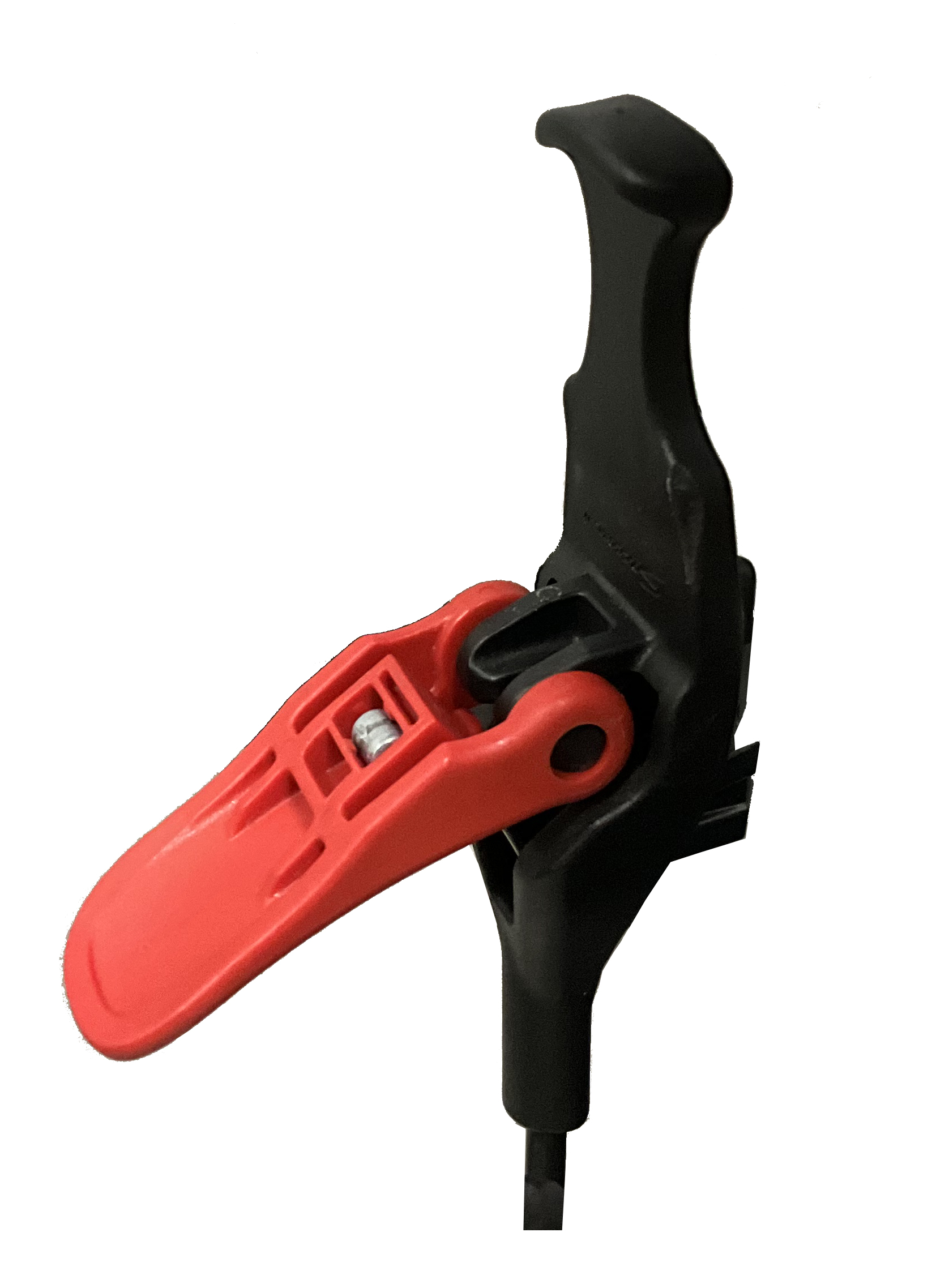
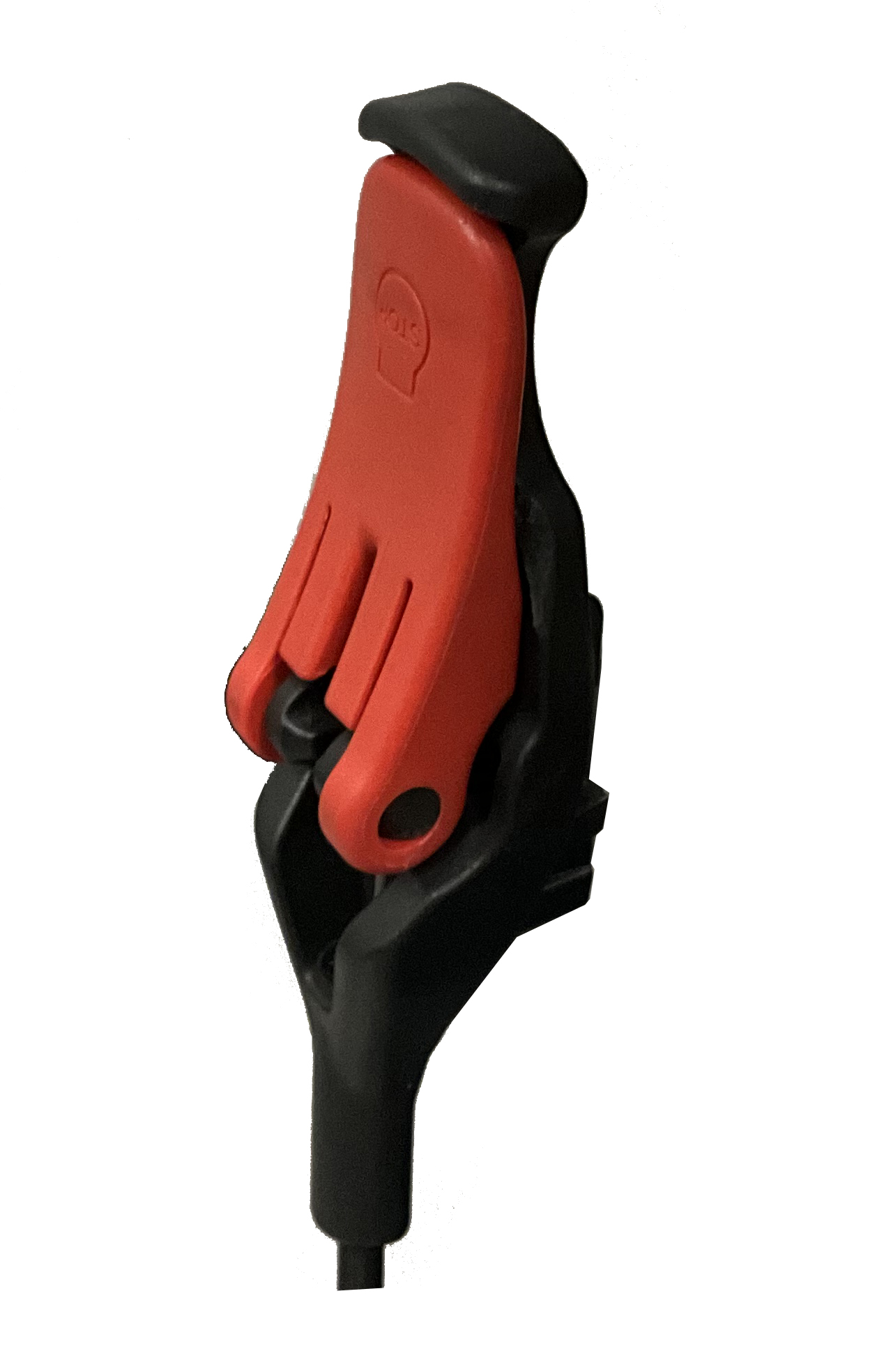
The two levers are snap-back. This means that pulling them back and rotating them allows the handle’s position to be adjusted. This is convenient for when the previous position conflicts with other devices or the floor, but it can be confusing at first. Simply remember that rotating the levers inward stops the motors, while rotating them outward activates them. |
The used batteries are 2 x 12VDC 17Ah. The batteries can remain constantly connected to the charger without any risk of overcharging.
If, for any reason, the batteries do not allow the descent operation, refer to Chapter 14, Manual activation of the actuator in case of emergency (STAND-UP ST, STAND-UP EE, STAND-UP ETM)
|
|


5.1.2. (STAND-UP ST, STAND-UP EE)
Battery charging and testing process
The STAND-UP ST and STAND-UP EE are shipped with the seat and backrest partially raised. Before using the device for the first time, it is recommended to perform a preliminary test, checking the battery charge level and performing a complete elevation and descent cycle as follows:
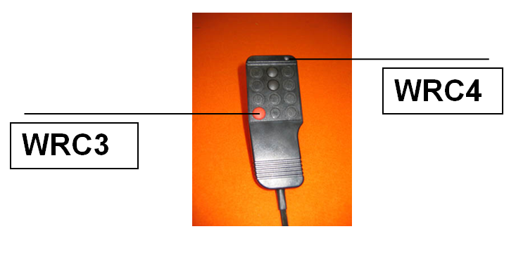
Press the red button WRC3 on the control keyboard and check the battery charge level using the LED WRC4:
-
If WRC4 is green, the battery is at least 80% charged.
-
If WRC4 is yellow, the battery is charged between 60% and 80%.
-
If WRC4 is red: the battery is low and can only operate for 5/10 elevation/descent cycles.
The used batteries are 2 x 12VDC 1.3Ah. The batteries can remain constantly connected to the charger without any risk of overcharging.
If, for any reason, the batteries do not allow the descent operation, refer to Chapter 14, Manual activation of the actuator in case of emergency (STAND-UP ST, STAND-UP EE, STAND-UP ETM)
Elevation and descent test (STAND-UP ST, STAND-UP EE)
STAND-UP is shipped with the seat and backrest partially elevated. Before using the stabilizer for the first time, it is recommended to perform an elevation and descent test as follows, but without the user in position.
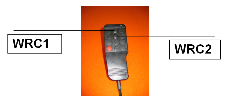
-
DESCENT: Press the WRC2 button to lower the seat to a horizontal position.
-
ELEVATION: Press the WRC1 button to raise the seat to a vertical position.
-
DESCENT: Press the WRC2 button again to return the seat to a horizontal position.
If a problem occurs during this test, refer to Chapter 14, Manual activation of the actuator in case of emergency (STAND-UP ST, STAND-UP EE, STAND-UP ETM)
If necessary, contact OFFCARR’s technical support.
5.2. Quick-Release Check (HAPPY STANDING)
|
|
Before using the device, make sure to verify the proper functioning of the quick-release devices. |
Normally, the device is shipped with the wheels already mounted.
However, it is necessary to check the correct operation of the quick-release mechanism and the proper attachment of the wheels to the frame before using the device.
|
|

|
|
For safety reasons, it is important to repeat this check every time the rear wheels are assembled. |
5.3. Tyre pressure check (HAPPY STANDING)
A periodical check of the tyre pressure helps to keep the device efficient and more comfortable
Verify the tyre pressure value according to the value marked on the tyre. Indicatively the maximum pressure for the most common wheels is:
-
7.5 bar (750 kPa - 110 psi) for high pressure wheels
|
|
With pneumatic tyres, it is recommended to reduce their pressure in the case of air transport, to avoid collateral effects of pressure variations due to altitude. |
5.4. Parking Brake Check
5.4.1. HAPPY STANDING
To check the proper operation and effectiveness of the parking brakes:
-
Activate the brakes (position ON).
-
Ensure that the wheels are locked.
Front Brake Activated, ON position |
Front Brake at Rest, OFF position |
|
|
Rear Brake Activated, ON position |
Rear Brake at Rest, OFF position |
|
|
|
|
The availability of different types of brakes may be limited by the chosen configuration. Not all brakes are compatible with all configurations. |
|
|
The provided brakes are for parking purposes only and should not be used as service brakes. |
|
|
To ensure the efficiency of the brakes, it is necessary to maintain proper tire pressure and regularly check for wear on the locking elements. |
5.4.2. STAND-UP EE
The parking brake on the front wheels acts with a locking lever on the propulsion pulleys.
To activate the brakes, pull the lever A towards the user, to deactivate push the lever A away from the user. |
|

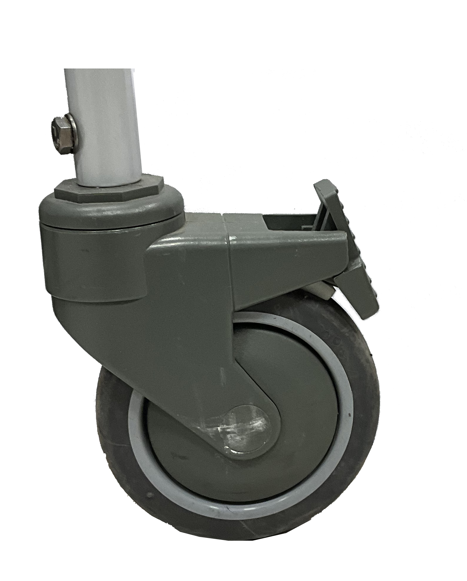
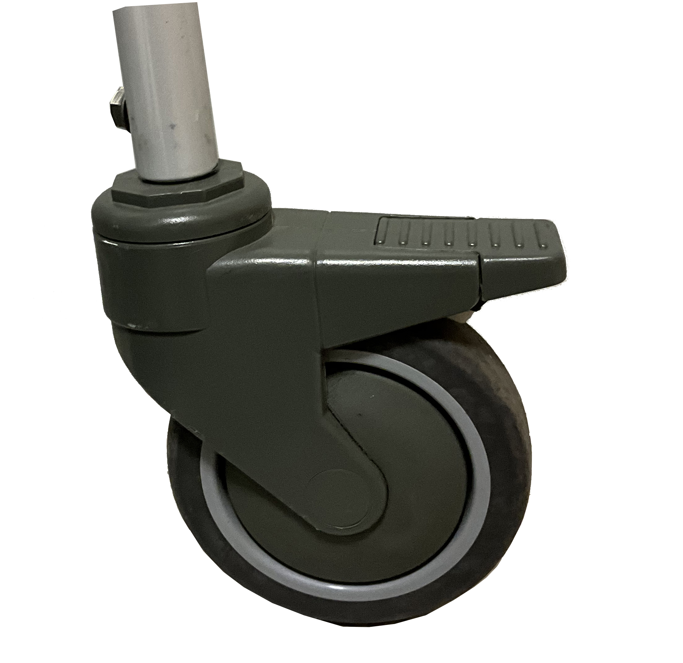
To check the proper operation and effectiveness of the rear parking brakes:
-
Activate the brakes (position ON).
-
Ensure that the wheels are locked.
Rear Brake Activated, ON position |
Rear Brake at Rest, OFF position |
|
|
5.4.3. STAND-UP ETM
While the motors are connected to the wheel (see 13.1, “HAPPY STANDING”), the also act as parking brakes on the front wheels.
To check the proper operation and effectiveness of the rear parking brakes:
-
Activate the brakes (position ON).
-
Ensure that the wheels are locked.
Rear Brake Activated, ON position |
Rear Brake at Rest, OFF position |
|
|
5.5. Accessories check
Some accessories required when setting up the device may be supplied separately. You must assemble them and check their operation before you start using the device.
6. Maintenance, inspections and controls
Weekly:
HAPPY STANDING
-
✓ Check the tyre pressure.
-
✓ Check the efficiency of the parking brakes.
-
✓ Check the stability of the chest supports, knee supports and other accessories.
-
✓ Check if all the adjustment screws are tight.
STAND-UP ST, STAND-UP EE, STAND-UP ETM
-
✓ Check the battery charge level.
-
✓ Check the efficiency of the seat movement and if necessary proceed with the lubrication of the connections.
-
✓ Check the stability of the chest supports, knee supports and other accessories.
-
✓ Check if all the adjustment screws are tight.
Quarterly:
HAPPY STANDING, STAND-UP ST, STAND-UP EE, STAND-UP ETM
-
✓ Lubricate moving parts such as hinges, bearings and axles. It is suggested to use silicon oil, which is efficient and doesn’t smear.
|
|
Only choose original parts when purchasing accessories or spare parts. Contact OFFCARR if you can’t find original spare parts on the market elsewhere. |
|
|
It is recommended to refer only to authorized and qualified personnel to perform maintenance programs, adjustments, and to replace components or accessories. |
6.1. Replacement of tyre and inner tube (HAPPY STANDING)
6.1.1. Removing the tyre and inner tube
|
|
|
|
|
|
|
|


6.1.2. Assembling the inner tube and tyre
|
|

6.2. Replacing Pushing Wheel Bearings (HAPPY STANDING)
Disassembly
|

|
Assembly
|
6.3. Quick extraction devices (HAPPY STANDING)
6.3.1. Check
The quick extraction axles are shipped already checked and adjusted. However, it is recommended to periodically verify the effectiveness of their operation.
|
|
6.3.2. Adjustment
If necessary, it is possible to adjust the axle to eliminate any play between the wheel and the frame or to complete the release of the button once the wheel is inserted. |
|

-
If the quick-release button is not completely relaxed when the wheel is inserted in the frame, it is necessary to extend the useful length of the L axle by partially unscrewing the Y nut.
-
If once the wheel has been inserted into the frame, there is play between the frame and the wheel itself, it is necessary to reduce the useful length of the L axis by partially tightening the Y nut.
|
|
The Y nut thread has a pitch of 1 mm, therefore the unscrewing or screwing of one turn involves the elongation or reduction of 1 mm. In case of adjustment, it is advisable to proceed with successive adjustments of ¼ of a turn at a time. |
7. Troubleshooting (STAND-UP ST, STAND-UP EE, STAND-UP ETM)
FAULT |
DIAGNOSIS |
PROBABLE SOLUTION |
Slow elevation |
Batteries are low |
Perform a recharge cycle of at least 6 hours. |
Elevation not working |
Batteries are low Vertical limit switch active (closed) |
Perform a recharge cycle of at least 6 hours. Remove the switch from its position and test the elevation. If the elevation works, check the efficiency of the switch and proceed with its reassembly or, if necessary, replacement. |
The actuator descent doesn’t work |
Batteries are low Lower limit switch active (closed) |
Place the seat in a horizontal position by connecting the battery charger to the power grid and perform a recharge cycle of at least 6 hours. Remove the switch from its position and test the descent. If the descent works, check the efficiency of the switch and proceed with its reassembly or, if necessary, replacement. If the actuator still doesn’t work, refer to section 14 “Manual activation of the actuator in case of emergency” |
The control keyboard doesn’t work, and the WRC4 light doesn’t turn on |
Batteries are low or damaged Damaged connecting wire Damaged keyboard |
Connect the battery charger to the line. If the keyboard works, recharge the batteries or contact technical support for possible battery replacement. Check the wire connecting the keyboard to the control unit and replace it if damaged. Replace the keyboard. |
The joystick communicates error codes through flashing LEDs. |
System error. |
Contact OFFCARR customer support service. |
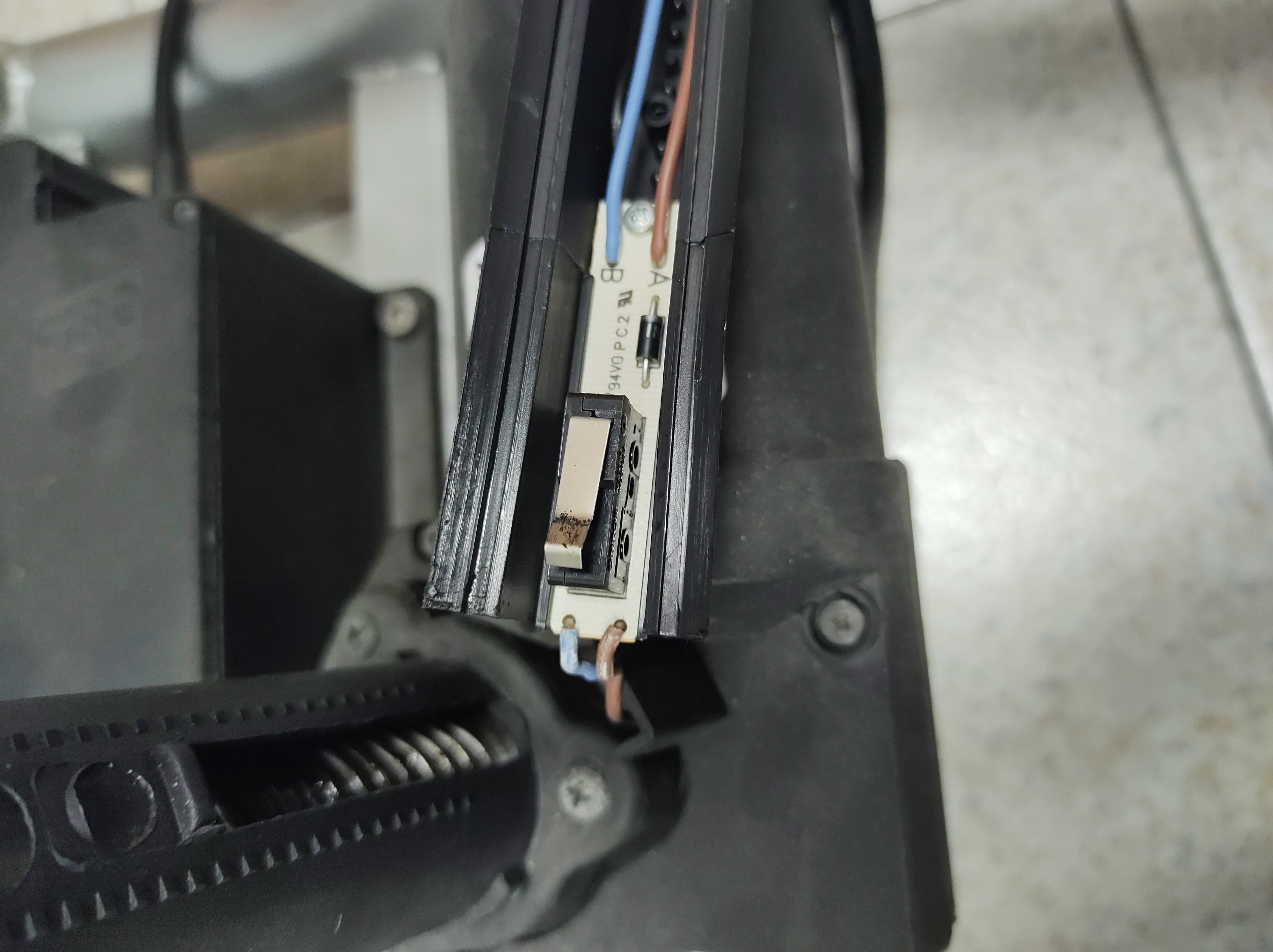
7.1. Limit switches
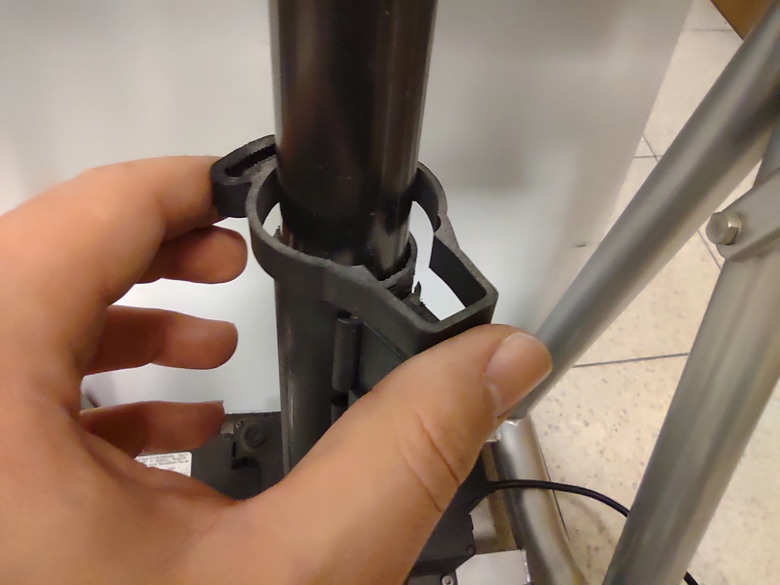
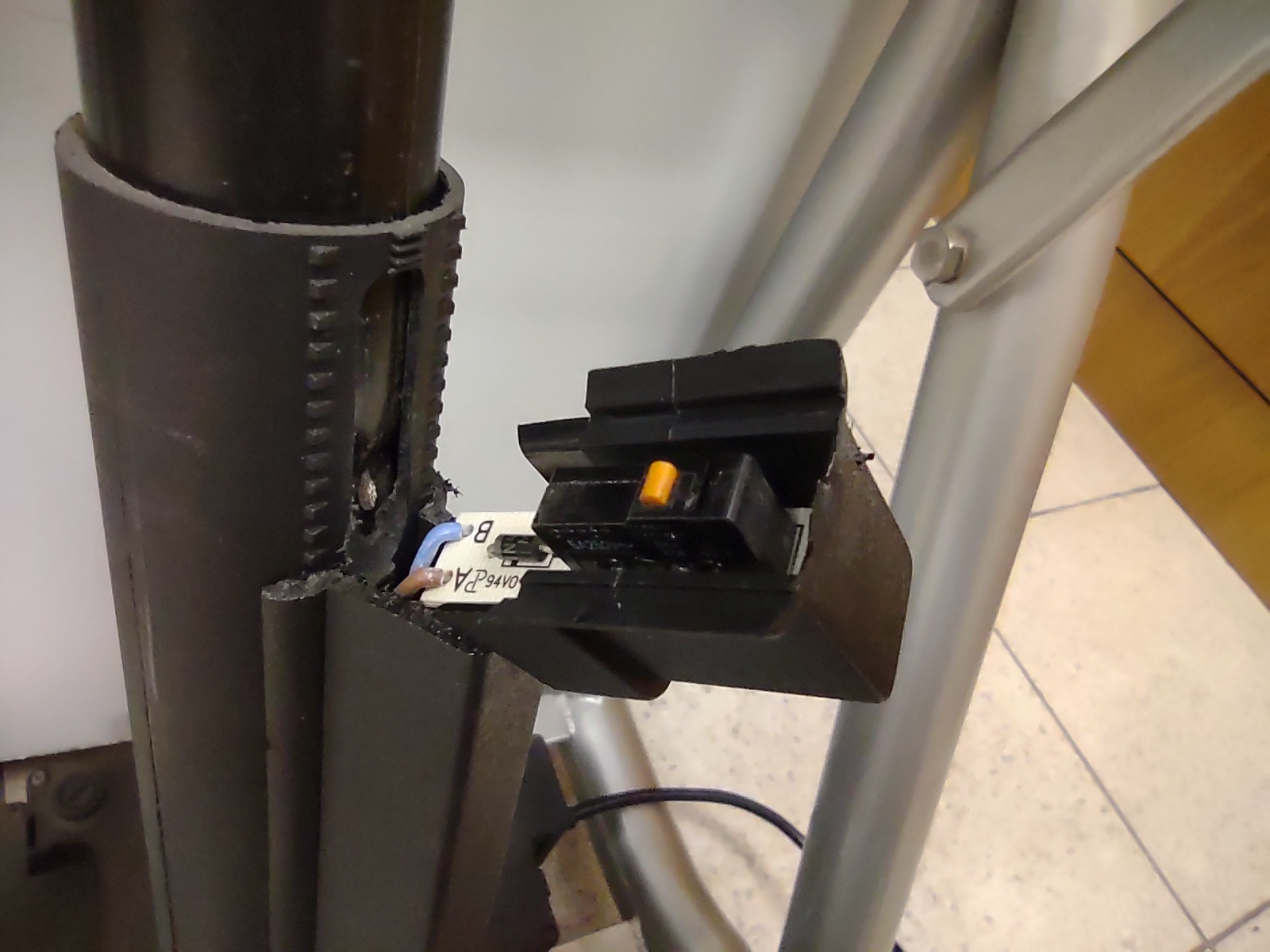
7.1.1. Upper limit switch check
|
|
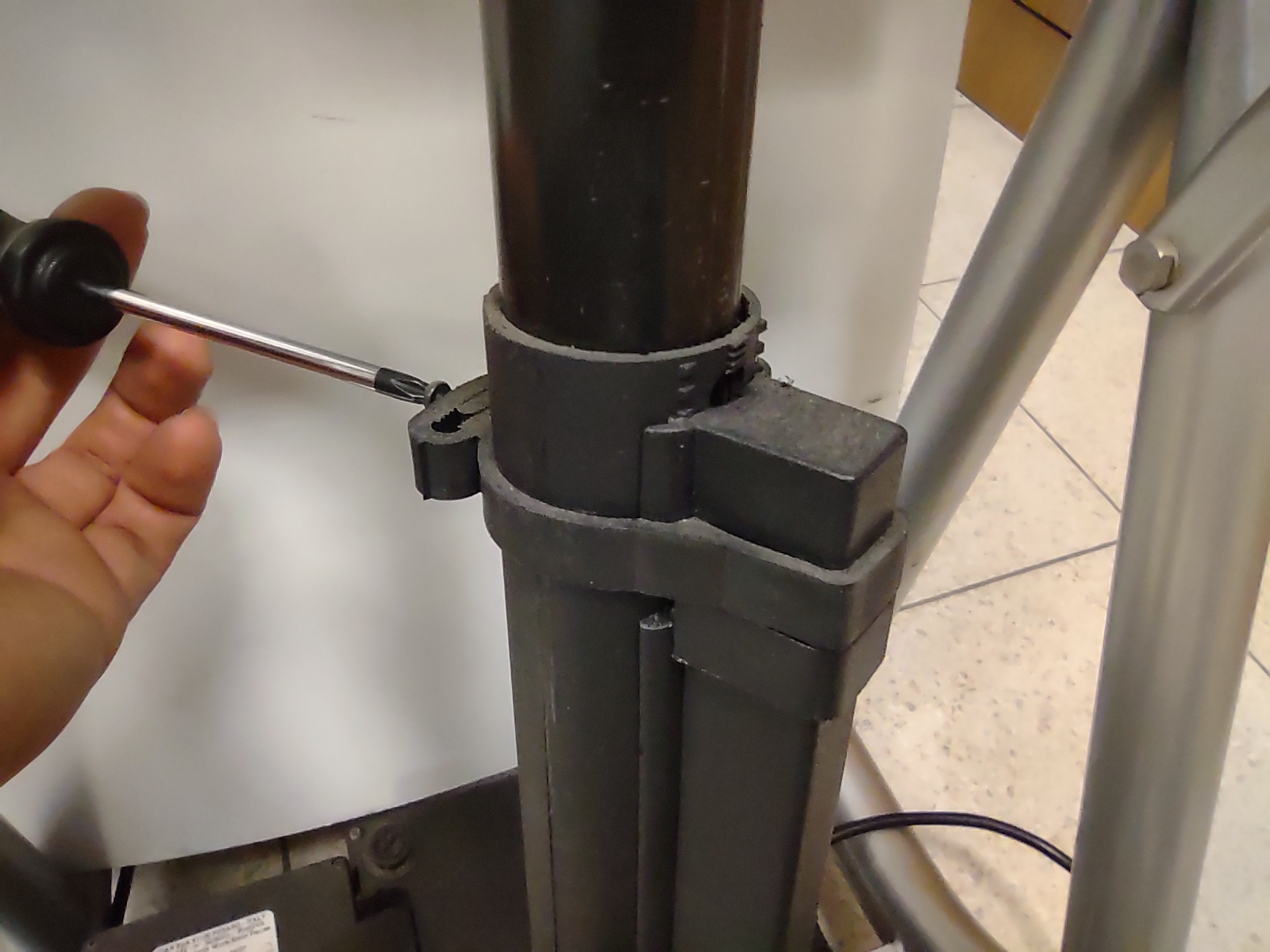
1. Remove the screw holding the upper switch clamp |
2. Unhook the plastic clamp |
|
|
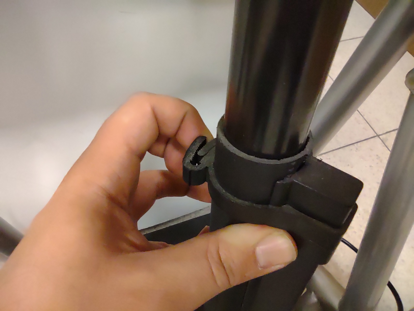
3. Remove the plastic clamp |
4. Check the switch behaviour |

|
|
With the upper limit switch depressed, the elevation should work both upwards and downwards, with the switch released the elevation should only work downwards |
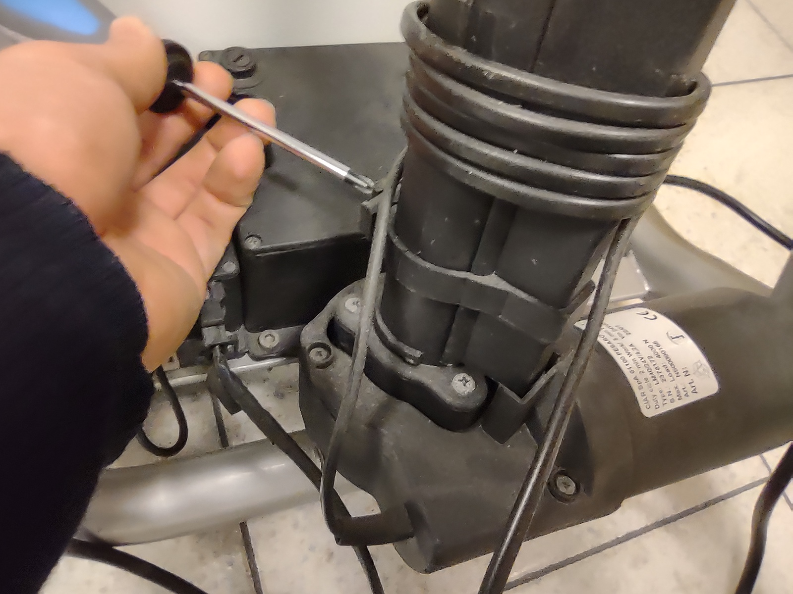
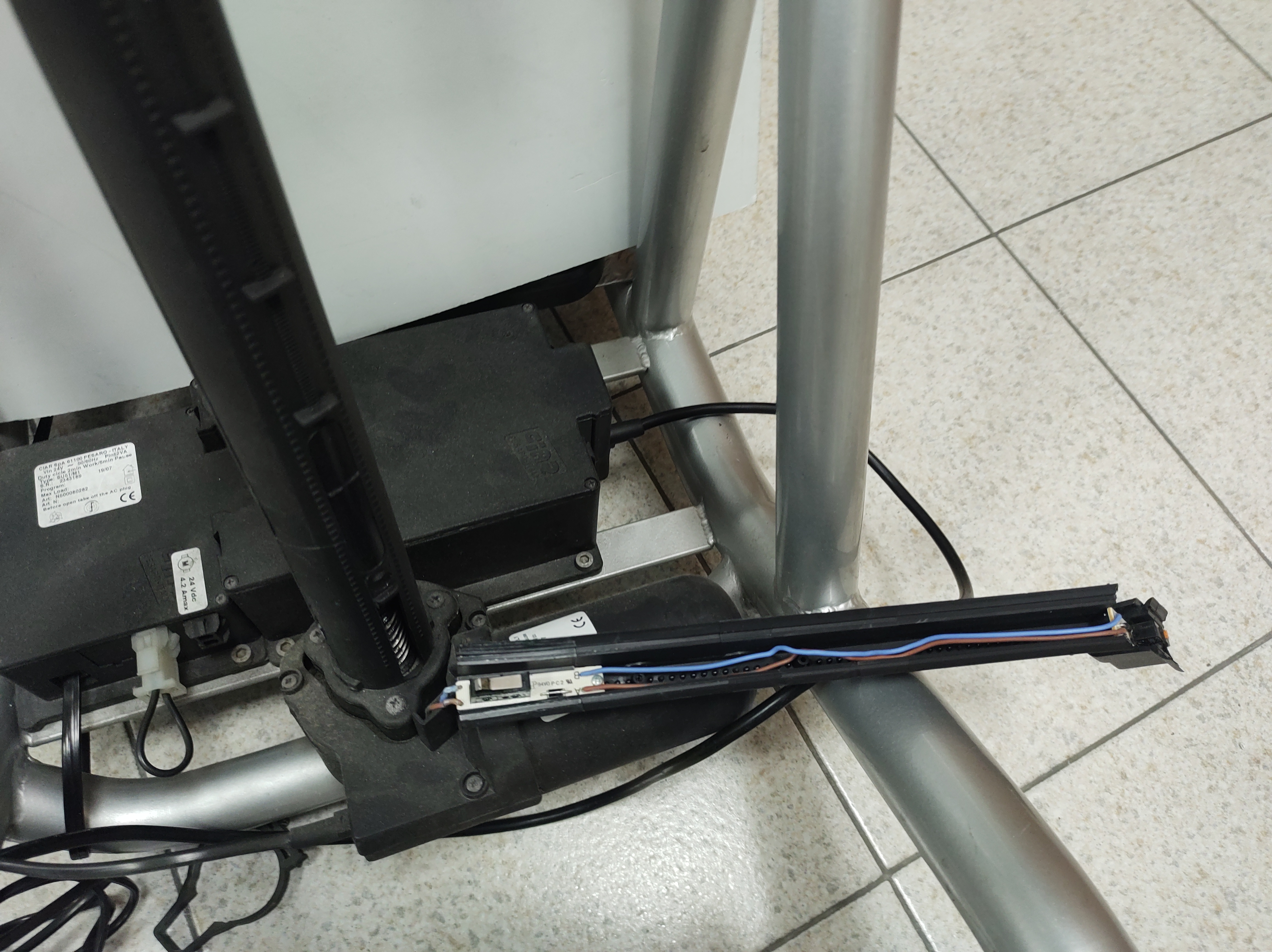
7.1.2. Lower limit switch check
|
|
1. Remove the upper limit switch clamp |
2. Remove the screw holding the lower switch clamp |
|
|
3. Unhook the lower plastic cover adn expose the lower switch |
4. Check the switch behaviour |
|
|
While keeping the upper switch depressed: with the lower limit switch depressed, the elevation should should only work upwards, with the switch released the elevation should work both upwards and downwards. |
8. Cleaning instruction
|
|
Cleaning and disinfection procedure have to be performed exclusively by qualified personnel. |
|
|
Follow the instructions on this manual to perform the cleaning and disinfection procedure. |
|
|
Use appropriate eye/facial protection and protective gloves, during cleaning and disinfection procedure. |
In case of contamination with blood or other body fluids, the device has to be cleaned first and then disinfected as follows:
|
|
Most of the time is convenient and more effective to remove the upholstery from the frame before to proceed with the cleaning and disinfection of either frame or upholstery. |
FRAME
-
Wash the device with lukewarm water and neutral detergent using a damp cloth to remove gross soiling
-
Remove eventual detergent residuals only with lukewarm water
-
Dry the device prior to further processing
-
Visually inspect the cleanliness of the complete device
-
Disinfect the device using 70-90% alcohol
-
Be sure it is completely dry before proceeding with use
|
|
Never recharge the batteries during maintenance operations. |
|
|
During the cleaning process the device should be also carefully inspected for damage, oxidation and faults in function. If any damage or faults are found, the involved components should be removed for service, repair or replacement. |
|
|
All waste materials related to this process must be disposed in compliance with specific local applicable law. |
9. Technical service
For any service request, please contact OFFCARR supplying the following indications:
-
Model
-
Serial number
-
Fault description
-
Any reference or order number, if available, recorded on the order form.
-
Dealer
Every component of the device is available as spare part.
10. Warranty terms
It is strongly advised to register the product on the website www.offcarr.com after delivery.
-
The device’s frame is guaranteed for 3 (three) years from the delivery date.
-
The batteries are guaranteed for 6 (six) months from the delivery date.
-
The label showing the serial number, the manufacturer address and the CE symbol cannot be removed for any reason to preserve the warranty validity.
-
Parts subject to normal wear and tear are not covered by the warranty, unless specific wear is caused by evident manufacturing fault.
-
During the warranty period OFFCARR may proceed at its own discretion to change or to repair the faulty parts.
-
The warranty does not cover damage due to negligence, carelessness, misuse or by incorrect maintenance performed by non authorized personnel.
-
If any damage occurred during transport, the forwarder company is the only responsible. It is important to inform immediately both the forwarder company and, for information, OFFCARR.
-
The warranty does not cover injury or any other damage to people or goods connected to the device’s malfunctioning.
11. Packaging, shipment and delivery
All OFFCARR products are shipped in closed cardboard cases to protect them from bumps and dust.
The package includes the device configured according with the order form, this Instruction manual and a tool kit.
The device must be transported in trucks that protect it from atmospheric agents, as shown on the packaging box.
Upon receipt, check the box integrity: open the package, remove the device and check it for damages. In case of problems, note your remark on the waybill and immediately notify both the forwarder and, for information, OFFCARR.
Once these checks, mandatory to ensure the validity of the warranty, have been carried out, place again the device in its packing until it is used and store in a cool and dry place (between - 15 and + 50 °C and with a relative humidity lower than 80 %).
Do not place any objects over the packaging box.
The packaging materials follow the European directive 94/62/EC[13].
12. Correct disposal and recycling
OFFCARR products are made of aluminium alloy (Al 7020, Al 6082, Al 2017, Al 6061, Al 5754), titanium, steel, stainless steel, carbon fibre, polyurethane, epoxy resins, other composite materials.
Recycle or disposal of all materials must be in compliance with the local applicable laws.
Contact your dealer in case of doubt or for help when disposing the device.
13. Adjustments
|
|
Please refer to authorized and qualified personnel to perform the adjustments described in this manual. |
13.1. HAPPY STANDING
Unresolved directive in ../lingue/en/modelli/stabilizzatori/12_setup_stabilizzatori.adoc - include::../../../modelli/happy_standing/adjustments.adoc[leveloffset=+1]
13.2. STAND-UP ST, STAND-UP EE, STAND-UP ETM
|
|
For correct use and proper adjustment, consult a therapist or other qualified personnel |
|
|
Especially at the beginning, qualified personnel’s assistance is essential to avoid any inconvenience. In some cases, upright positioning can create excessive load on the lower limbs and may require a personalized rehabilitation program. Especially at the beginning, the user may experience balance problems due to the unusual upright position. In this case, qualified personnel’s assistance is required for a rehabilitation program. |
|
|
For safety reasons, always perform every ascent and descent operation with the parking brakes engaged. |
13.2.1. Adjustment of the heel-stops
Before using for the first time, it is advisable to proceed with the adjustment of the heel-stops as follows:
|
|

Velcro foot straps can be installed upon request.
13.2.2. Adjustment of the knee supports
|
|
The positioning of the knee supports should be done under the supervision of a therapist or qualified personnel. For safety reasons, any adjustments should be made with the parking brakes engaged. Perfect the adjustment with the user seated and proceed as follows: |
HEIGHT ADJUSTMENT:
|
|
DEPTH ADJUSTMENT:
WIDTH ADJUSTMENT:
|
|


13.2.3. Adjustment of the chest support
If necessary, proceed with the adjustment of the chest support as follows:
HEIGHT ADJUSTMENT:
|
|
DEPTH ADJUSTMENT:
|
|


Now proceed with the user’s first elevation under the supervision of a therapist or qualified personnel, ensuring that:
-
The parking brakes are engaged.
-
The feet are stable and properly secured by the heel-stops.
-
The knee supports are in the correct position.
|
|
The actuator is active in elevation as long as the WRC1 button is pressed. Therefore, the control of the ascent must be operated manually by the person managing the control keyboard. The actuator is equipped with two limit switches (see 7.1, “Limit switches”). One determines the horizontal position (seated) and automatically stops the movement even if the WRC2 button continues to be pressed. The other controls the vertical position (upright), but in most cases, it is necessary to manually stop the elevation releasing the pressure from the WRC1 button before reaching the limit to avoid excessive pressure of the body on the chest support. |
13.2.4. Adjustment of the table
The table should be adjusted with the user in an upright position; therefore, it is necessary to execute the user’s first elevation. This should be done under the supervision of a therapist or qualified personnel, ensuring that:
-
The feet are stable and properly secured by the heel-stops.
-
The knee supports are in the correct position.
|
|
The actuator is activated and controlled via a joystick. During the ascent, it is advisable to constantly monitor the user’s balance. |
|
|
The actuator is equipped with two limit switches (see 7.1, “Limit switches”). One determines the horizontal position (seated), while the other controls the vertical position (upright). In most cases, it is necessary to halt the elevation before reaching the limit switch to prevent excessive pressure on the chest against the chest support. |
The table’s position is subjective and depends on how the user intends to use it. Once the person is in an upright position, you can proceed with the table adjustment as follows:
|
|

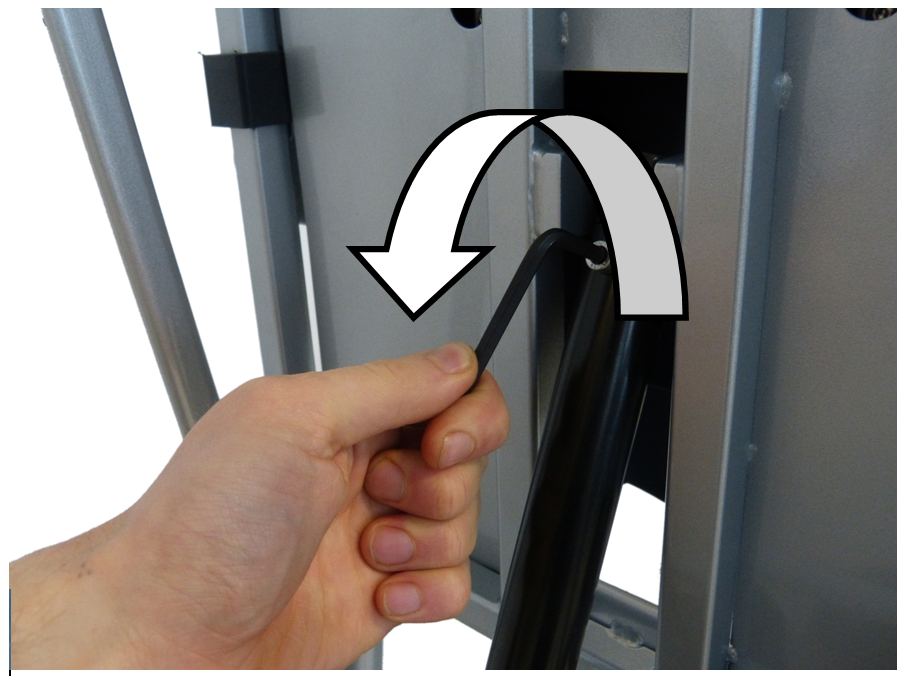
14. Manual activation of the actuator in case of emergency (STAND-UP ST, STAND-UP EE, STAND-UP ETM)
|
|
When performing this operation, be extremely careful never to completely detach the actuator from the joint. |
In case the user is in an upright position and due to a malfunction of the control board, the descent operation is not possible, it becomes necessary to manually intervene to return the user to a seated position. In this case, proceed as follows:
|
|
|
|
|
|
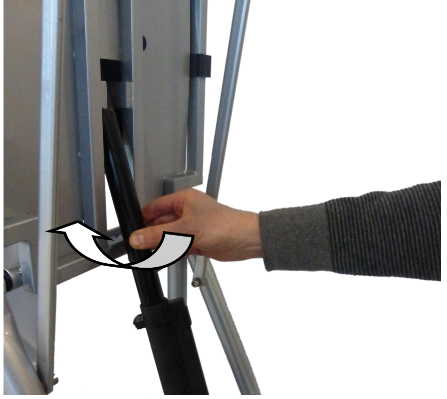
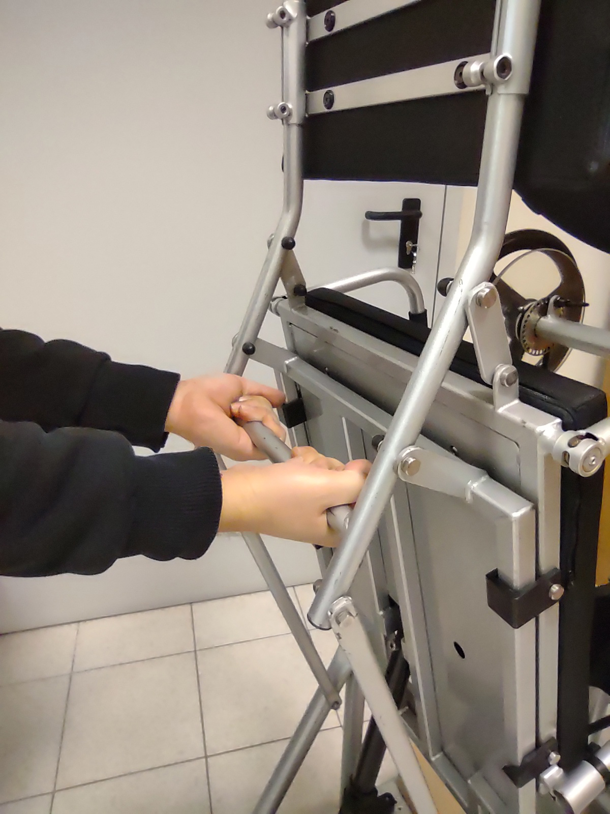
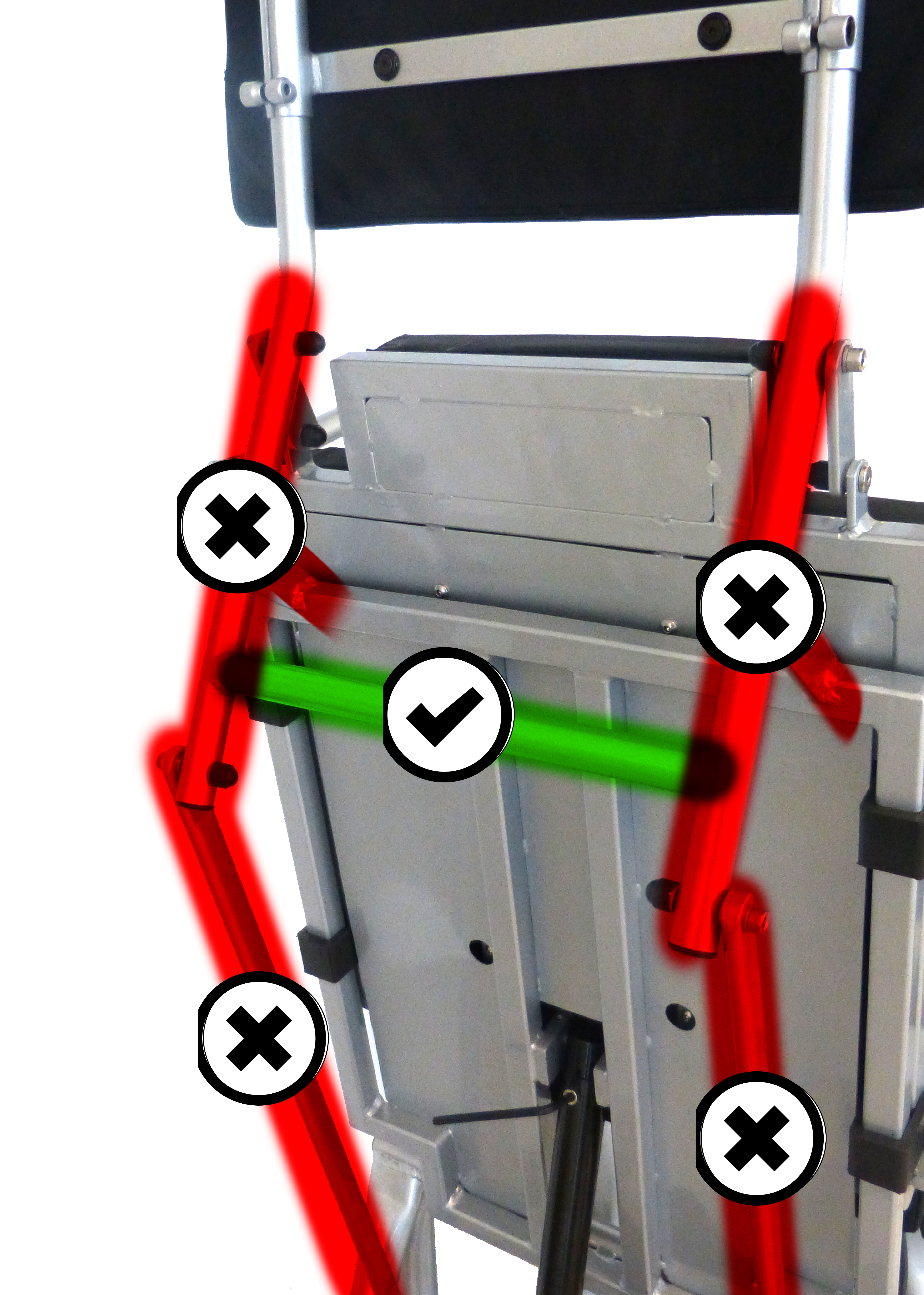
To facilitate manual operation on the actuator, you can partially support the seat to avoid putting the entire load on the axis of the actuator to be turned. Exercise extreme caution and avoid excessive lifting that could dislodge the joint from the actuator and prevent supporting the entire user’s weight. |
|
|
When performing the EMERGENCY operation, be mindful to avoid crushing fingers and hands between the mechanical arms. |
|
|
Support the seat only by the back horizontal bar (indicated in the previous pictures) and avoid the vertical bars! |
|
|
How to relief some load out of the actuator |
|
-
To restore the device’s features, reinsert the removed components.
If necessary, consult OFFCARR Service Assistance or qualified personnel before performing the operation.
OFFCARR s.r.l. reserves the right to make improvements and/or changes on its products, at any time without prior notice, with respect of the device features, suitability, certifications, warranty contract and availability of spare parts according to the terms of law.