Table of Contents
- 1. Labelling
- 2. Using the device
- 3. Warnings to reduce any risks associated with misuse of the device
- 4. Product presentation
- 5. Preparation for use
- 5.1. Wheelchair opening
- 5.2. Wheelchair folding
- 5.3. Wheelchair opening (QPX)
- 5.4. Wheelchair folding (QPX)
- 5.5. Backrest opening and closing (QPX)
- 5.6. Inserting / removing the armrests (QPX)
- 5.7. Inserting / removing the side-guards (QPX)
- 5.8. Rear wheels release and re-engagement check
- 5.9. Tyre pressure check
- 5.10. Brakes check
- 5.11. Footrest positioning
- 5.12. Accessories check
- 6. Accessories
- 6.1. Armrests
- 6.2. Anti-tip device
- 6.3. Single drive
- 6.4. Hinged backrest
- 6.5. Lever-activated small wheels for narrow passages
- 6.6. Tip assist pedal
- 6.7. Extended wheel plates
- 6.8. Stretch bar
- 6.9. Elevating footrest
- 6.10. Table
- 6.11. Swing away lateral supports
- 6.12. Headrest
- 6.13. Pelvic band installation
- 6.14. Spokes guards
- 7. Attachment of the wheelchair for use within a motor vehicle
- 8. Maintenance, inspections and controls
- 9. Cleaning instruction
- 10. Technical service
- 11. Warranty terms
- 12. Packaging, shipment and delivery
- 13. Correct disposal and recycling
- 14. Adjustments
- 14.1. Seat Depth Adjustment (CHILDREN 3000, CHILDREN3000 PLUS, VEGA3000)
- 14.2. Width Adjustment (CHILDREN 3000 PLUS)
- 14.3. Width adjustment (VEGA3000)
- 14.4. Seat Length Adjustment
- 14.5. Front Seat Cover Length Adjustment
- 14.6. Rear seat height adjustment
- 14.7. Gravity centre (COG) adjustment
- 14.8. Rear wheels camber adjustment
- 14.9. Rear wheels camber adjustment
- 14.10. Front seat height adjustment
- 14.11. Front fork support plate perpendicularity adjustment
- 14.12. Brakes adjustment
- 14.13. Side-guard adjustment
- 14.14. Side-guard adjustment (QPX)
- 14.15. Backrest tilt angle adjustment
- 14.16. Backrest tension adjustment
- 14.17. Seat upholstery adjustment and replacement
- 14.18. Backrest height adjustment, pushing handles adjustment
- 14.19. Height adjustable pushing handles adjustment
- 14.20. Footrest height adjustment
- 14.21. Footplate tilt adjustment
- 14.22. Pushrim with rivets
- 14.23. Pushrim with splices
- 14.24. Anti-tip device adjustment on curved rear frames
- 14.25. Anti-tip adjustment on straight rear frames
- 14.26. CHILDREN3000 Anti-Tip Adjustment
- 14.27. Height adjustment for lever-activated small wheels
- 14.28. Table installation
- 14.29. Abductor assembly
- 14.30. Assembly and adjustment of swing-away lateral supports
Thanks for choosing an OFFCARR product.
OFFCARR listens and responds to the customers' needs by engineering highly technical, innovative solutions aimed at reducing daily mobility problems, with special attention to product style and to improving quality of life.
OFFCARR has a certified system for quality management following UNI EN ISO 9001 regulations and a Medical Device - Quality management system following UNI EN ISO 13485 regulations.
OFFCARR products comply with the european medical device regulation UE MDR 2017/745.

|
Before using or making adjustments on this device, read this instruction manual carefully. |
|
|
Different versions of this manual, accessible for various types of visual disabilities are available on www.offcarr.com |
Contact an authorized dealer or the manufacturer at the following address if clarification regarding the safety measures is required.
|
OFFCARR srl |

|
MADE IN ITALY |

|
Distributor: |
|
|


1. Labelling
Each OFFCARR product is identified by a unique serial number. The serial number, along with other information is visible on the product stickers applied to the frame.
|
Stickers position on the product frame |

|
Product sticker (applied on the frame) |
|
UDI sticker (applied on the frame and on the instructions for use) |


Information available on the product sticker: |
|
|
|
1.1. Symbols description
|
Please read all instructions before using the device. Read all Cautions and Warnings carefully. |
|
European Conformity - The symbol denotes conformity to European standards. |
|
WARNING: Read carefully and follow the indications. |
|
NOTE: Auxiliary information. |
|
Medical Device |
|
UDI: Unique Device Identifier |
|
Serial Number |
|
Reference - The symbol indicates the model of the product. |
|
The symbol indicates the country of origin. |
|
The symbol indicates the distributor of the product. |
|
The symbol indicates the manufacturer of the product. |
|
The symbol indicates the maximum load permissible for the product. |
|
The symbol denotes the attachment points for crash tested models. |
|
The symbol denotes the importance of protecting the packaging and the product from harsh weather. |
|
The symbol denotes that shipment must be performed with care and the package must always be kept and stored with the arrows pointing upwards. |


2. Using the device
|
|
In order to move safely and properly use the device, it is always recommended to consult qualified personnel. |
Hereafter are some suggestions for a correct use of the device, also aimed to maintain the characteristics of safety and durability over time:
-
The brakes only have a parking purpose and should never be used as service brakes to slow down the device in motion.
-
Do not lean too far forward, because by moving the centre of gravity, the device could tip-over.
-
The device should be used only in accordance with what is proposed in this manual and not of objects in general.
-
Always deal with slopes above 6° with assistance from an attendant. This limit is only approximate and it depends on the specific configuration of the device, especially on the position of the centre of gravity of the user-wheelchair combination.
-
To ensure the efficiency of the brakes, maintain the tyres properly inflated and quarterly check the knurled locking pin wear.
-
Never use the anti-tip devices, if available, as transit wheels.
-
The armrests, if available, are not designed to lift the device.
-
Avoid wheeling the device without the supervision of an attendant.
-
Perform a general check of the device at least every three months, by checking tyre inflation, efficiency of the quick-release axles and brakes; lubricate the moving parts whenever necessary.
-
If necessary, the upholstery can be washed with water at low temperature. Avoid wetting or submerging other parts of the device.
-
Prolonged contact of the device with water or prolonged exposure to high humidity levels can cause unwanted oxidation of some metal parts and decay of the security features of the materials involved.
-
Avoid contact with seawater and sand. In case of contact proceed to an immediate and accurate cleaning.
-
Clean periodically the device using a damp cloth and avoid even partial immersion of the frame. Keeping the device clean enhances its efficiency.
|
|
Suspend the use of the product and notify OFFCARR in case of allergic reactions or if other similar problems are developed after contact with the device materials. |
|
|
There is no apparent danger of causing injury to people during the operations of preparation and setup of the device if carried out according to the instructions provided in this manual. |
|
|
Make sure the tyres are correctly inflated. Since the correct pressure differs between models, read the required pressure on the side of the tyre itself. |
|
|
The pressure of the Schwalbe Marathon Plus tyres should always be kept from a minimum of 7 bar (700 kPa - 100 psi) to a maximum of 9 bar (900 kPa - 130 psi) to prevent damage to the covers themselves. |
|
|
Keep the device away from heat sources, as not all the components are fireproof. |

|
Upholstery materials comply with the EN 1021-2:2014 regulation. |
|
|
The approximate lifespan of the device is 7 years, considering correct, normal daily use by a single user and regular maintenance. |
3. Warnings to reduce any risks associated with misuse of the device
|
|
It is forbidden to use the device or its parts in different ways from those described on this manual. |
|
|
When opening or closing the wheelchair, pay attention to the position of the fingers (see 5.1, “Wheelchair opening”) to avoid being pinched and possibly injured between the frame and the crossbar tubes. |
|
|
Do not use the brakes, if available, to slow down the device at any speed. They are only designed as parking devices. |
|
|
Do not use the armrests, if available, to pick the device up or as clamping spots. |
|
|
Never use the anti-tip devices, if available, as transit wheels. It is not their intended purpose. |
|
|
It is suggested to frequently check the working order of the quick-release wheel devices, especially after each insertion. |
|
|
The gap between wheels and side-guards or brakes could be lower than 25 mm. Be careful not to put your fingers between the wheels and side-guards or brakes to avoid injury. |
|
|
With pneumatic tyres, it is recommended to reduce their pressure in the case of air transport, to avoid collateral effects of pressure variations due to altitude. |
|
|
To maintain the device efficient and maintain its safety requirements it is recommended to uphold a regular upkeep schedule, as described by this manual. |
|
|
Poor maintenance and improper use of the device can cause damage or injury to the user or assistant. |
|
|
Any tampering with the components of the device, as well as voiding the warranty, could compromise its structural integrity and safety standards. |
|
|
Contact OFFCARR in case the maximum user weight is exceeded at any point during the device’s lifespan. |
|
|
Contact OFFCARR or your reseller to check for compatibility with accessories produced by a manufacturer different from OFFCARR. |
|
|
Do not install on the device mechanical or electronic devices that are not approved by OFFCARR and do not modify its structure in any way. Any combination with other medical devices must be authorized by OFFCARR. In case the combination has been approved, always refer to the respective manuals. |
|
|
The device and its accessories are not suitable for use in hyperbaric chambers under any circumstances. |
|
|
In case of prolonged exposure to the sun, the surface of the device can reach high temperatures. |
|
|
To have more information about connection points and devices needed to secure the device during transport by car (exclusively valid for crash tested models) see Chapter 7, Attachment of the wheelchair for use within a motor vehicle |
|
|
Before transferring to or from the device, activate the parking brakes. Always perform transfers with caution. |
|
|
Some openings in the device may have angles lower than 75° (e.g. space between wheel spokes) or gaps smaller than 25 mm (e.g. gaps between spokes). |
|
|
For technical and aesthetic reasons the pushing handles may be placed at a height lower than 900 mm from the ground. |
|
|
Headrests (optional) are not approved for use as headrests on moving vehicles. |
|
|
The tip assist pedal and anti-tip devices are optional accessories that must be requested when ordering the device. |
|
|
Do not exceed the weight limit of the devices even temporarily. For example, do not perform activities such as weightlifting on the devices. |
|
|
Use the device and its parts exclusively for their intended purpose. |
|
|
The device is suitable for use by children and teenagers; however, adult supervision is recommended. |
4. Product presentation
4.1. ALHENA
Alhena are non-invasive medical devices specifically designed to reduce and counterbalance motor impairments in the medium and long-term.
This wheelchair is manually propelled on the back wheels, it allows for many configurations and a wide range of accessories to meet the needs of users.
Only qualified operators must setup the device.
|
|
It is forbidden to use the device or its parts in different ways from those described in this manual. |
4.1.1. Description
|
|

4.1.2. Features
-
Ultralightweight wheelchair
-
Titanium folding frame
-
Titanium double crossbar
-
Two angle-shaped front frame
-
Multiple positions for rear wheels
-
Tilt adjustable front fork support
-
Carbon fibre side-guards
-
Foldable and detachable armrests (if selected on the setup)
-
Footrest according to the choice during setup
-
Different kind of side-guards and armrests
-
The order form allows different setups and various combinations of accessories.
-
Maximum load: 120 kg
4.1.3. Measurements table
All dimensions are in degrees (°) and millimetres (mm), the weight is expressed in kilograms (kg).
ALHENA |
Reference values |
|
Seat angle |
0° ÷ 20° |
|
Backrest angle |
90° |
|
Leg angle |
90° - 76° |
|
Total width |
max 740 (L46 - 4°) |
7001 |
Total length |
max 1200 (P46) |
12001 |
Total height |
max 1100 |
12001 |
Pivot turn width |
max 1650 |
13001 |
Turn width |
max 1300 |
10001 |
Weight2 |
9,7 |
All dimensions refer to wheelchairs in standard configuration
The addition of accessories may modify the indicated dimensions and weight
1 Some dimensions may exceed the reference values according to UNI EN 12183. In some circumstances and with certain configurations, the use of safety exits may be complicated or impossible
2 The weight depends on the selected configuration and may vary based on accessories.
4.1.4. Rear wheel and pushrim diameter
The table indicates diameter of rear wheels and relative pushrims.
| Rear wheel diameter | Pushrim outer diameter (average) |
|---|---|
24" |
535 mm |
25" |
550 mm |
4.1.5. Front wheel diameter
| Front wheel options | |
|---|---|
80 mm |
solid |
100 mm |
solid |
125 mm |
solid |
150 mm |
solid or pneumatic |
Unresolved directive in ultralight_folding.adoc - include::../lingue/shared/modelli/Children3000/variabili.adoc[]
4.2. CHILDREN3000, CHILDREN3000 PLUS
Children3000, Children3000 Plus are non-invasive medical devices specifically designed to reduce and counterbalance motor impairments in the medium and long-term.
Only qualified operators must setup the device.
|
|
It is forbidden to use the device or its parts in different ways from those described in this manual. |
4.2.1. Description
4.2.2. CHILDREN3000 Features
-
Super lightweight wheelchair
-
Foldable aluminium alloy frame
-
Adjustable frame and seat depth (+ 60 mm compared to the ordered size, up to 38 cm)
-
Adjustable backrest height
-
Double adjustable crossbar width
-
Straight or abducted front frame
-
Fixed or removable footrests (or removable and elevating upon technical compatibility assessment)
-
Foot adjustment Device (FaD) for footplates
-
Various side-guards as specified in the configuration sheet
-
Rear wheel plate adjustable in multiple positions
-
Tilt-adjustable front forks
-
Available with single-drive configuration
-
Maximum user weight: 75 kg
-
CRASH TESTED: suitable for use in motor vehicles
4.2.3. CHILDREN3000 PLUS Features
-
Super lightweight wheelchair
-
Foldable aluminium alloy frame
-
Adjustable frame and seat depth (+ 60 mm compared to the ordered size, up to 38 cm)
-
Adjustable frame width (based on the selected size on the sheet)
-
Adjustable backrest height
-
Double adjustable crossbar width
-
Straight or abducted front frame
-
Fixed or removable footrests (or removable and elevating upon technical compatibility assessment)
-
Foot adjustment Device (FaD) for footplates
-
Various side-guards as specified in the configuration sheet
-
Rear wheel plate adjustable in multiple positions
-
Adjustable front forks in tilt
-
Available with single-drive configuration
-
Maximum user weight: 75 kg
-
CRASH TESTED: suitable for use in motor vehicles
4.2.4. Measurements table
All dimensions are in degrees (°) and millimetres (mm), the weight is expressed in kilograms (kg).
Unresolved directive in <stdin> - include::../lingue/shared/modelli/Children3000/dimensions.adoc[lines=2..3] |
Reference values |
|
Seat angle |
Unresolved directive in <stdin> - include::../lingue/shared/modelli/Children3000/dimensions.adoc[lines=6..7] |
|
Backrest angle |
Unresolved directive in <stdin> - include::../lingue/shared/modelli/Children3000/dimensions.adoc[lines=10..11] |
|
Leg angle |
Unresolved directive in <stdin> - include::../lingue/shared/modelli/Children3000/dimensions.adoc[lines=14..15] |
|
Total width |
Unresolved directive in <stdin> - include::../lingue/shared/modelli/Children3000/dimensions.adoc[lines=18..19] |
7001 |
Total length |
Unresolved directive in <stdin> - include::../lingue/shared/modelli/Children3000/dimensions.adoc[lines=22..23] |
12001 |
Total height |
Unresolved directive in <stdin> - include::../lingue/shared/modelli/Children3000/dimensions.adoc[lines=26..27] |
12001 |
Pivot turn width |
Unresolved directive in <stdin> - include::../lingue/shared/modelli/Children3000/dimensions.adoc[lines=30..31] |
13001 |
Turn width |
Unresolved directive in <stdin> - include::../lingue/shared/modelli/Children3000/dimensions.adoc[lines=34..35] |
10001 |
Weight2 |
Unresolved directive in <stdin> - include::../lingue/shared/modelli/Children3000/dimensions.adoc[lines=38..39] |
All dimensions refer to wheelchairs in standard configuration
The addition of accessories may modify the indicated dimensions and weight
1 Some dimensions may exceed the reference values according to UNI EN 12183. In some circumstances and with certain configurations, the use of safety exits may be complicated or impossible
2 The weight depends on the selected configuration and may vary based on accessories.
4.2.5. Rear wheel and pushrim diameter
The table indicates diameter of rear wheels and relative pushrims.
| Rear wheel diameter | Pushrim outer diameter (average) |
|---|
4.2.6. Front wheel diameter
| Front wheel options |
|---|
4.2.7. Attachment of the wheelchair for use within a motor vehicle: CHILDREN3000
|
CHILDREN3000 is equipped with four (4) attachment points A for a standard 4-point floor anchoring system, as shown in the diagram. When connecting the wheelchair to a vehicle, attach the fastening system to the four designated connection points marked with the appropriate symbol. These are the sturdiest contact points of the wheelchair and the only ones certified by crash testing. |

4.3. DIVA
Diva are non-invasive medical devices specifically designed to reduce and counterbalance motor impairments in the medium and long-term.
This wheelchair is manually propelled on the back wheels, it allows for many configurations and a wide range of accessories to meet the needs of users.
Only qualified operators must setup the device.
|
|
It is forbidden to use the device or its parts in different ways from those described in this manual. |
The medical device DIVA, if provided with vehicle attachments correctly installed is CRASH TESTED and can be used in any vehicle provided of an adequate retaining system.
All configurations of DIVA comply to the following standards:
-
ISO 7176-8
-
ISO 7176-16
-
ISO 7176-19 (only with the optional accessories kit)
4.3.1. Description
|
|

4.3.2. Features
-
Ultralight wheelchair
-
Aluminium folding frame
-
Single or double crossbar (with some limitation of configuration)
-
Multiple positions for backrest tilt (if selected on order)
-
Multiple positions for rear wheels
-
Tilt adjustable front fork support
-
Different kind of side-guards and armrests
-
Fixed or detachable footrests or elevating and detachable
-
Single drive available
-
Maximum load: 120 kg
4.3.3. Measurements table
All dimensions are in degrees (°) and millimetres (mm), the weight is expressed in kilograms (kg).
DIVA |
Reference values |
|
Seat angle |
0° ÷ 25° |
|
Backrest angle |
86° ÷ 121° |
|
Leg angle |
(90° ÷ 5°X) |
|
Total width |
max 750 |
7001 |
Total length |
max 1150 (max 950Y) |
12001 |
Total height |
max 1050 |
12001 |
Pivot turn width |
1450 |
13001 |
Turn width |
1460 |
10001 |
Weight2 |
from 11,5 kg |
All dimensions refer to wheelchairs in standard configuration
The addition of accessories may modify the indicated dimensions and weight
1 Some dimensions may exceed the reference values according to UNI EN 12183. In some circumstances and with certain configurations, the use of safety exits may be complicated or impossible
2 The weight depends on the selected configuration and may vary based on accessories.
4.3.4. Rear wheel and pushrim diameter
The table indicates diameter of rear wheels and relative pushrims.
| Rear wheel diameter | Pushrim outer diameter (average) |
|---|---|
24" |
535 mm |
25" |
550 mm |
4.3.5. Front wheel diameter
| Front wheel options | |
|---|---|
80 mm |
solid |
100 mm |
solid |
125 mm |
solid |
150 mm |
solid or pneumatic |
4.3.6. Attachment of the wheelchair for use within a motor vehicle: DIVA
|
DIVA is provided with four (4) attachment points A for a standard 4-point floor tiedown system, as indicated in the figure. When connecting the wheelchair to a vehicle, connect the attachment system to the four marked connection points. These are the most solid points of contact on the wheelchair, and the only connection points certified by the crash test. |

4.4. EMERALD
Emerald are non-invasive medical devices specifically designed to reduce and counterbalance motor impairments in the medium and long-term.
This wheelchair is manually propelled on the back wheels, it allows for many configurations and a wide range of accessories to meet the needs of users.
Only qualified operators must setup the device.
|
|
It is forbidden to use the device or its parts in different ways from those described in this manual. |
4.4.1. Description
|
|

4.4.2. Features
-
Ultra-lightweight wheelchair
-
Foldable aluminium frame
-
Single crossbar (or double only for depths of 34 and 36 cm)
-
Straight or abducted front frame.
-
Fixed or removable footrests
-
Various side-guards as specified in the configuration sheet
-
Rear wheels adjustable in multiple positions
-
Front forks adjustable in tilt
-
Available with single-drive configuration
-
Maximum load capacity: 75 kg
4.4.3. Measurements table
All dimensions are in degrees (°) and millimetres (mm), the weight is expressed in kilograms (kg).
EMERALD |
Reference values |
|
Seat angle |
0° ÷ 25° |
|
Backrest angle |
90° ÷ 115° |
|
Leg angle |
90° ÷ 60° |
|
Total width |
max 580 ( L36 - camber 1°) |
7001 |
Total length |
max 950 |
12001 |
Total height |
max 1000 |
12001 |
Pivot turn width |
max 1690 |
13001 |
Turn width |
max 1250 |
10001 |
Weight2 |
11 |
All dimensions refer to wheelchairs in standard configuration
The addition of accessories may modify the indicated dimensions and weight
1 Some dimensions may exceed the reference values according to UNI EN 12183. In some circumstances and with certain configurations, the use of safety exits may be complicated or impossible
2 The weight depends on the selected configuration and may vary based on accessories.
4.4.4. Rear wheel and pushrim diameter
The table indicates diameter of rear wheels and relative pushrims.
| Rear wheel diameter | Pushrim outer diameter (average) |
|---|---|
20" |
445 mm |
22" |
480 mm |
24" |
535 mm |
4.4.5. Front wheel diameter
| Front wheel options | |
|---|---|
80 mm |
solid |
100 mm |
solid |
125 mm |
solid |
150 mm |
solid or pneumatic |
4.5. HALLEY/HALLEY.Ti
Halley are non-invasive medical devices specifically designed to reduce and counterbalance motor impairments in the medium and long-term.
This wheelchair is manually propelled on the back wheels, it allows for many configurations and a wide range of accessories to meet the needs of users.
Only qualified operators must setup the device.
|
|
It is forbidden to use the device or its parts in different ways from those described in this manual. |
The medical device HALLEY is available in 2 variations, described by this manual:
HALLEY: the aluminium frame version
HALLEY.Ti: the titanium frame version
4.5.1. Description
|
|

4.5.2. HALLEY Features
-
Ultralight wheelchair
-
Aluminium folding frame
-
Double crossbar
-
Multiple positions for rear wheels
-
Tilt adjustable front fork support
-
Different kind of side-guards and armrests
-
Fixed or detachable footrests
-
Maximum load: 120kg
4.5.3. HALLEY.TI Features
-
Ultralight wheelchair
-
Titanium folding frame
-
Double crossbar
-
Multiple positions for rear wheels
-
Tilt adjustable front fork support
-
Different kind of side-guards and armrests
-
Fixed or detachable footrests
-
Maximum load: 120kg
4.5.4. Measurements table
All dimensions are in degrees (°) and millimetres (mm), the weight is expressed in kilograms (kg).
HALLEY |
Reference values |
|
Seat angle |
0° ÷ 20° |
|
Backrest angle |
90° |
|
Leg angle |
90° - 76° |
|
Total width |
max 720 (L44 - 4°) |
7001 |
Total length |
max 1200 (P46) |
12001 |
Total height |
max 1100 |
12001 |
Pivot turn width |
max 1650 |
13001 |
Turn width |
max 1300 |
10001 |
Weight2 |
12,4 |
All dimensions refer to wheelchairs in standard configuration
The addition of accessories may modify the indicated dimensions and weight
1 Some dimensions may exceed the reference values according to UNI EN 12183. In some circumstances and with certain configurations, the use of safety exits may be complicated or impossible
2 The weight depends on the selected configuration and may vary based on accessories.
4.5.5. Rear wheel and pushrim diameter
The table indicates diameter of rear wheels and relative pushrims.
| Rear wheel diameter | Pushrim outer diameter (average) |
|---|---|
24" |
535 mm |
25" |
550 mm |
4.5.6. Front wheel diameter
| Front wheel options | |
|---|---|
80 mm |
solid |
100 mm |
solid |
125 mm |
solid |
150 mm |
solid or pneumatic |
4.6. QPX-AL, QPX-TI
The ultra-lightweight wheelchairs QPX are non-invasive medical devices, specifically designed to reduce and counterbalance a physical handicap. These wheelchairs, manually propelled on the back wheels, have many setups and a wide range of accessories that meet any customer need.
The medical device QPX is available in 2 variations, described by this manual:
QPX-AL: the aluminium frame version
QPX-TI: the titanium frame version
QPX-AL, QPX-TI are non-invasive medical devices specifically designed to reduce and counterbalance motor impairments in the medium and long-term.
This wheelchair is manually propelled on the back wheels, it allows for many configurations and a wide range of accessories to meet the needs of users.
Only qualified operators must setup the device.
|
|
It is forbidden to use the device or its parts in different ways from those described in this manual. |
4.6.1. Description
|
|

4.6.2. QPX-AL Features
-
Aluminium frame with aluminium crossbar
-
Adjustable rear wheel placement to better adjust the centre of gravity
-
Carbon fibre side-guard, eventually removable (optional)
-
Self closing carbon fibre footplate
-
L removable armrests (optional)
-
Foldable backrest
-
Locking system for the folded position
-
Maximum weight supported: 100 Kg
4.6.3. QPX-TI Features
-
Titanium frame and aluminium crossbar
-
Adjustable rear wheel placement to better adjust the centre of gravity
-
Carbon fibre side-guard, eventually removable (optional)
-
Self closing carbon fibre footplate
-
L removable armrests (optional)
-
Foldable backrest
-
Locking system for the folded position
-
Maximum weight supported: 100 Kg
The order form includes all possible setups and accessories available for the QPX-TI and QPX-AL wheelchairs.
4.6.4. Measurements table
All dimensions are in degrees (°) and millimetres (mm), the weight is expressed in kilograms (kg).
QPX-AL, QPX-TI |
Reference values |
|
Seat angle |
0° ÷ 16° |
|
Backrest angle |
89° ÷ 93° |
|
Leg angle |
90° |
|
Total width |
max 740 (L46) |
7001 |
Total length |
max 880 (P46) |
12001 |
Total height |
max 950 (HP 48, HS 41) |
12001 |
Pivot turn width |
max 1600 |
13001 |
Turn width |
max 1300 |
10001 |
Weight2 |
10,3 (38x40) |
All dimensions refer to wheelchairs in standard configuration
The addition of accessories may modify the indicated dimensions and weight
1 Some dimensions may exceed the reference values according to UNI EN 12183. In some circumstances and with certain configurations, the use of safety exits may be complicated or impossible
2 The weight depends on the selected configuration and may vary based on accessories.
4.6.5. Rear wheel and pushrim diameter
The table indicates diameter of rear wheels and relative pushrims.
| Rear wheel diameter | Pushrim outer diameter (average) |
|---|---|
24" |
535 mm |
25" |
550 mm |
4.6.6. Front wheel diameter
| Front wheel options | |
|---|---|
80 mm |
solid |
100 mm |
solid |
125 mm |
solid |
150 mm |
solid or pneumatic |
4.7. VEGA / VEGA.E
The lightweight wheelchair VEGA is a non invasive medical device, specifically designed to reduce and counterbalance a physical handicap. This wheelchair is manually propelled on the back wheels, it has many setups and a wide range of accessories that meet any customer need.
Vega are non-invasive medical devices specifically designed to reduce and counterbalance motor impairments in the medium and long-term.
This wheelchair is manually propelled on the back wheels, it allows for many configurations and a wide range of accessories to meet the needs of users.
Only qualified operators must setup the device.
|
|
It is forbidden to use the device or its parts in different ways from those described in this manual. |
The medical device VEGA is available in 2 variations, described by this manual:
VEGA: the standard version
VEGA.E: version with smaller front frame, only available with entirely detachable footrests that, when removed, shorten the wheelchair of around 50 mm compared to a same sized VEGA
4.7.1. Description
|
|

4.7.2. Features
-
Ultralight wheelchair
-
Aluminium folding frame
-
Double titanium crossbar (subject to limitations)
-
Multiple positions for rear wheels
-
Tilt adjustable front fork support
-
Different kind of side-guards and armrests
-
Fixed or detachable footrests or elevating and detachable
-
Single drive available
-
Maximum load: 120kg
4.7.3. Measurements table
All dimensions are in degrees (°) and millimetres (mm), the weight is expressed in kilograms (kg).
VEGA / VEGA.E |
Reference values |
|
Seat angle |
0° ÷ 25° |
|
Backrest angle |
90° |
|
Leg angle |
90° ÷ 70° (5°) |
|
Total width |
max 720 (L48 - 3°) |
7001 |
Total length |
max 1200 (P50 - COG 7) |
12001 |
Total height |
max 1050 |
12001 |
Pivot turn width |
max 1500 |
13001 |
Turn width |
max 1300 |
10001 |
Weight2 |
12,7 (38x38) |
All dimensions refer to wheelchairs in standard configuration
The addition of accessories may modify the indicated dimensions and weight
1 Some dimensions may exceed the reference values according to UNI EN 12183. In some circumstances and with certain configurations, the use of safety exits may be complicated or impossible
2 The weight depends on the selected configuration and may vary based on accessories.
4.7.4. Rear wheel and pushrim diameter
The table indicates diameter of rear wheels and relative pushrims.
| Rear wheel diameter | Pushrim outer diameter (average) |
|---|---|
24" |
535 mm |
25" |
550 mm |
4.7.5. Front wheel diameter
| Front wheel options | |
|---|---|
80 mm |
solid |
100 mm |
solid |
125 mm |
solid |
150 mm |
solid or pneumatic |
4.8. VEGA3000
The lightweight VEGA3000 wheelchair is a non-invasive medical device, specifically designed to reduce and counterbalance physical disabilities, offering the possibility to accommodate any evolution of expansion or reduction of the user. It is a manually propelled wheelchair with rear-wheel drive, offering a wide range of accessories to meet any customer’s needs.
Vega3000 are non-invasive medical devices specifically designed to reduce and counterbalance motor impairments in the medium and long-term.
This wheelchair is manually propelled on the back wheels, it allows for many configurations and a wide range of accessories to meet the needs of users.
Only qualified operators must setup the device.
|
|
It is forbidden to use the device or its parts in different ways from those described in this manual. |
4.8.1. Description
|
|

4.8.2. Features
-
Super lightweight wheelchair
-
Foldable aluminium alloy frame
-
Adjustable frame and seat depth
-
Adjustable backrest height
-
Double adjustable crossbar width
-
Straight or abducted front frame
-
Fixed or removable footrests (or removable and elevating upon technical compatibility assessment)
-
Foot adjustment Device (FaD) for footplates
-
Various side-guards as specified in the configuration sheet
-
Rear wheel plate adjustable in multiple positions
-
Tilt-adjustable front forks
-
Available with single-drive configuration
-
Maximum user weight: 120 kg
4.8.3. Measurements table
All dimensions are in degrees (°) and millimetres (mm), the weight is expressed in kilograms (kg).
VEGA3000 |
Reference values |
|
Seat angle |
0° ÷ 23° |
|
Backrest angle |
90° ÷ 113° |
|
Leg angle |
90° ÷ 70° (90° ÷ 5° X) |
|
Total width |
max 650 |
7001 |
Total length |
max 1150 (max 1000 Y) |
12001 |
Total height |
max 1020 |
12001 |
Pivot turn width |
max 1450 |
13001 |
Turn width |
max 1100 |
10001 |
Weight2 |
from 12,5 |
All dimensions refer to wheelchairs in standard configuration
The addition of accessories may modify the indicated dimensions and weight
1 Some dimensions may exceed the reference values according to UNI EN 12183. In some circumstances and with certain configurations, the use of safety exits may be complicated or impossible
2 The weight depends on the selected configuration and may vary based on accessories.
4.8.4. Rear wheel and pushrim diameter
The table indicates diameter of rear wheels and relative pushrims.
| Rear wheel diameter | Pushrim outer diameter (average) |
|---|---|
24" |
535 mm |
25" |
550 mm |
4.8.5. Front wheel diameter
| Front wheel options | |
|---|---|
80 mm |
solid |
100 mm |
solid |
125 mm |
solid |
150 mm |
solid or pneumatic |
5. Preparation for use
|
|
The preparation for use of these devices must be performed by qualified personnel to ensure the specific suitability of the product for the user and the correct working order of all parts and accessories, as well as to provide clear instructions to the user. |
5.1. Wheelchair opening
Apply pressure with the open palm over the sides of the seat, as shown on the drawing, until the seat is perfectly aligned to the frame |
|

|
|
Place your hands only on the upper part of the seat support tubes without wrapping them to avoid crushing of the fingers during the opening operation |
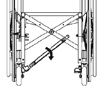
5.2. Wheelchair folding
If necessary, fold up the footplate(s) to allow the folding of the wheelchair frame Pull the seat upholstery upwards with both hands as shown on the drawing |
|

5.3. Wheelchair opening (QPX)
|
|
|
|
Pay attention to avoid any pinching of the fingers between the moving crossbar arms. Act only on the lock |
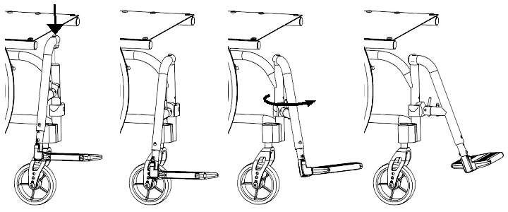
5.4. Wheelchair folding (QPX)
|
|
|
|
Note: If closing the wheelchair seems too hard, lift the footrest slightly on the not pivoted end. Doing so the closing process starts in a bit easier way and avoiding the force needed to start from the footrest completed open |
5.5. Backrest opening and closing (QPX)
|
|
The two backrest holders are independent, they both have to be closed at the same time |
5.5.1. Opening the backrest
|
|
5.5.2. Closing the backrest
|
|

|
|
Armrests should be removed before folding the backrest |
5.6. Inserting / removing the armrests (QPX)
L shaped armrest is the only removable armrest available for QPX wheelchairs. It’s revolving and removable and, depending on the setup, height adjustable.
5.6.1. Inserting the armrests
-
Place the lower part of the armrest onto its correct lodging
-
Make sure it is facing the right way and check the correct placement by verifying its stability.
5.6.2. Removing the armrests
-
When removing the armrest must be revolved backwards (even if partially) before it is removed from its lodging.
-
The armrest is not fundamental for the correct functioning of the wheelchair and can be removed while the user is sitting on the wheelchair.
|
|
Armrests should never be used to lift the wheelchairs, be it with or without the user. |
|
|
Armrests should be removed before folding the backrest. |
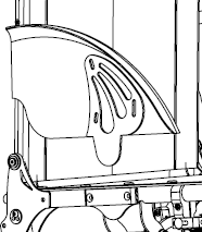
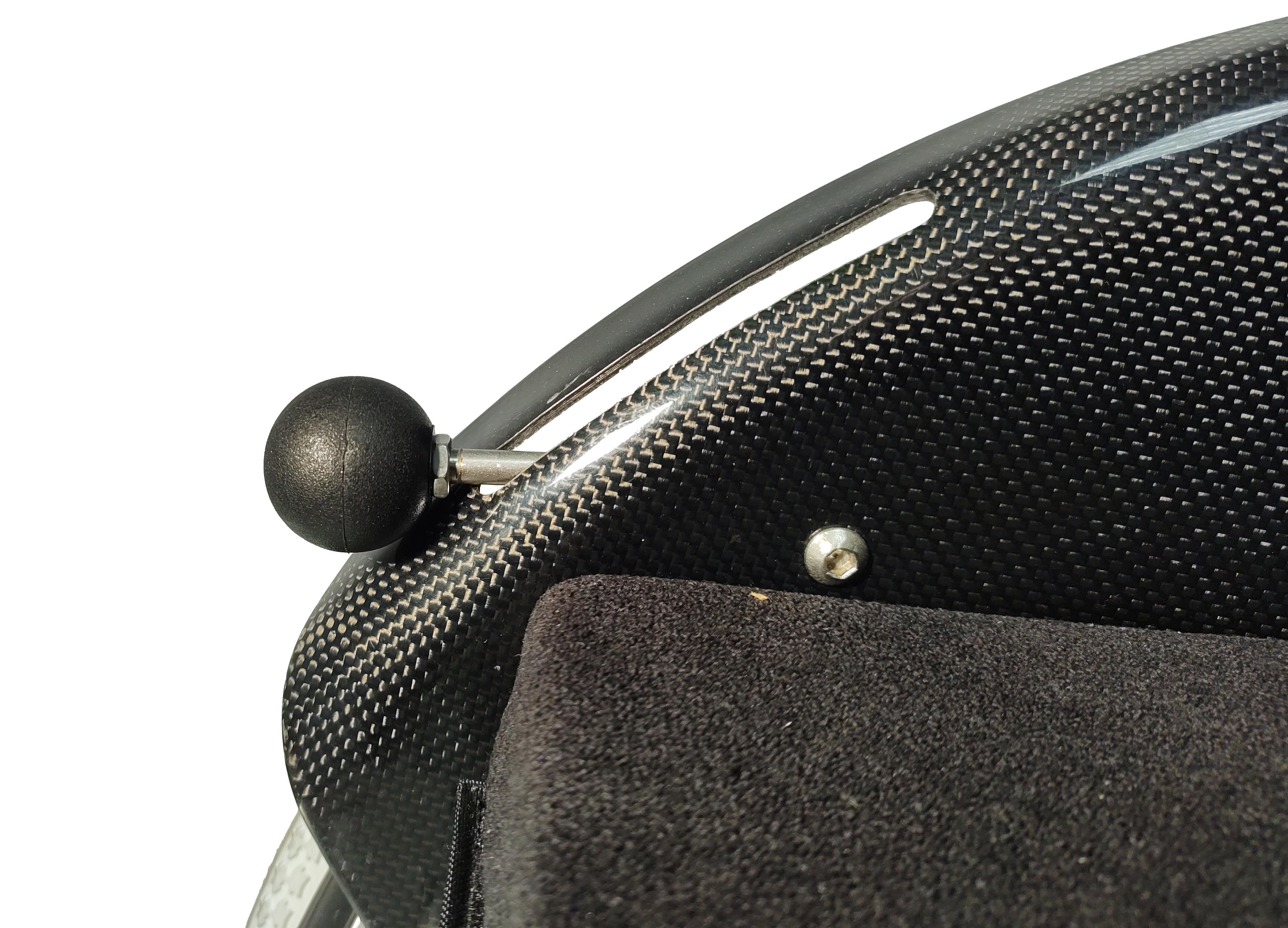
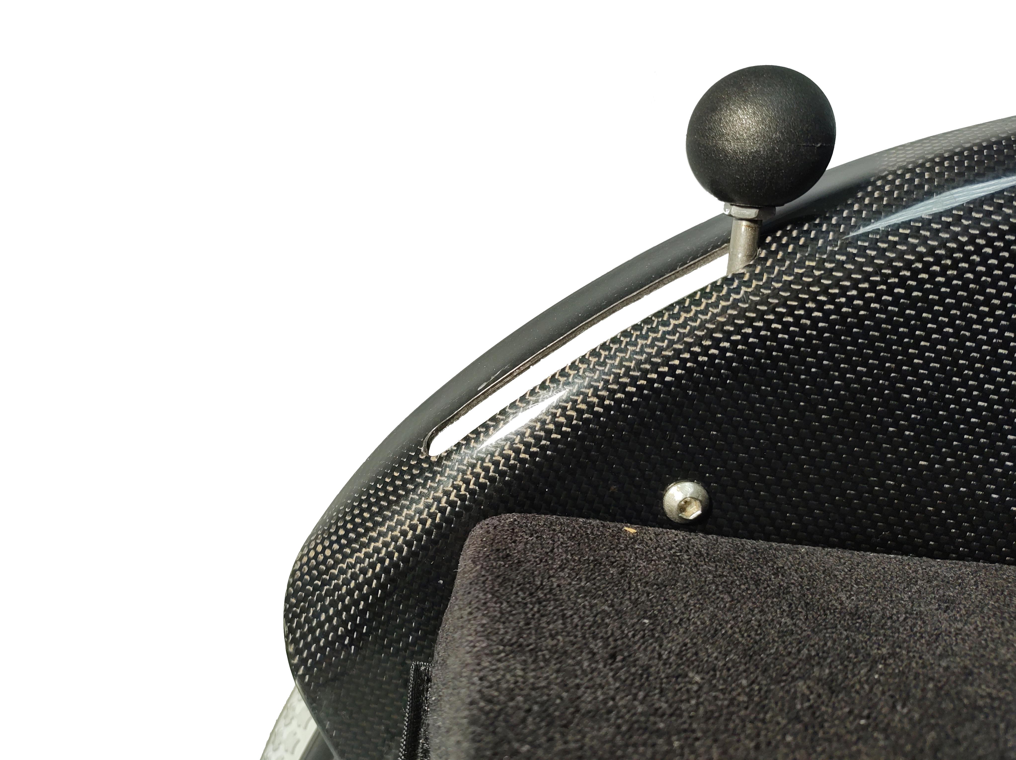
5.7. Inserting / removing the side-guards (QPX)
|
|
QPX models are available with carbon fibre side-guards. These can be fixed or removable, as chosen on the order form. Both cases leave a range of adjustments to compensate for any change of the rear wheel position. |
For removable side-guards:
|
|
|
|
|
Inserting and extracting the side-guards can be performed with the wheel both in place and not and even with the user sitting on the wheelchair. |
5.8. Rear wheels release and re-engagement check
|
|
Verify proper operation of the quick-release axle devices before using the wheelchair. |
The wheelchair is usually shipped with the rear wheels already mounted.
|
|

|
|
For safety reasons it is important to repeat this test every time that for transport or maintenance reasons, the rear wheels are removed and reassembled to the frame. |
5.9. Tyre pressure check
A periodical check of the tyre pressure helps to keep the device efficient and more comfortable
Verify the tyre pressure value according to the value marked on the tyre. Indicatively the maximum pressure for the most common wheels is:
-
7 to 9 bar (700÷900 kPa - 100÷130 psi) for Schwalbe Marathon Plus wheels
-
7.5 bar (750 kPa - 110 psi) for high pressure wheels
-
4.5 bar (450 kPa - 65 psi) for 20", 22", 24" x 1.3/8" wheels
-
2.5 bar (250 kPa - 30 psi) for pneumatic castor wheels
|
|
The pressure for the model Schwalbe Marathon Plus should always be kept from a minimum of 7 bar (700 kPa - 100 psi) to a maximum of 9 bar (900 kPa - 130 psi) to prevent damage to the lateral surface of the tyre itself. |
|
|
With pneumatic tyres, it is recommended to reduce their pressure in the case of air transport, to avoid collateral effects of pressure variations due to altitude. |
5.10. Brakes check
To check the correct functioning and the efficiency of the parking brakes:
-
activate the brakes (ON position)
-
check if the wheels are locked in place
|
|
Pushing brake ON position |
Pushing brake OFF position |


|
|
Pulling brake ON position |
Pulling brake OFF position |


|
|
Scissor brake ON position |
Scissor brake OFF position |


|
|
Composite brake ON position |
Composite brake OFF position |


|
|
Drum brake ON position |
Drum brake OFF position |


|
|
Single brake lever side ON position |
Single brake lever side OFF position |
|
|
Single brake opposite to lever side ON position |
Single brake opposite to lever side OFF position |


|
|
Side-guards brake ON position |
Side-guards brake OFF position |
|
|
Brake type availability is limited depending on the chosen configuration. Not all brake types are available for every setup. |
|
|
The included brakes, except for the assistant-activated brakes (drum), must be used exclusively as parking brakes and never as service brakes. |
|
|
To ensure the efficiency of the brakes it is necessary to maintain the proper tyre pressure and check the wear of the clamping elements frequently. |
5.11. Footrest positioning
OFFCARR wheelchairs can be configured with detachable or not detachable footrests
According to the limits of setup, the footplate can be single or double (separate footplates). The footplates can be folded down once the wheelchair is open
The single footplate is available in manual or automatic version. The automatic version, which follows the opening/folding of the wheelchair, is available only for non-detachable footrests frames.
After opening the wheelchair, manually bring the footplates to the correct position by rotating them downward. In case of single footplate, pay special attention to the engagement of the footplate on the frame on the side opposite the fulcrum.
Separate footplates |
Single footplate |
Automatic footplate |
|
|
|


|
|
In the absence of weight, even with the wheelchair open, the automatic fooplate remains slightly raised on one side. This condition is absolutely normal and allows the automatic closing. A slight weight on the plate is enough to make it assume the horizontal position. |
|
|
In case of removable footrests frame, the footrests are packed separately. They must be assembled before use. |
To insert the footrest:
-
open the wheelchair
-
insert the footrests in their correct housing and rotate them starting from a 90° angle position from the frame (as shown) and rotate it inwards until the hooking mechanism snaps
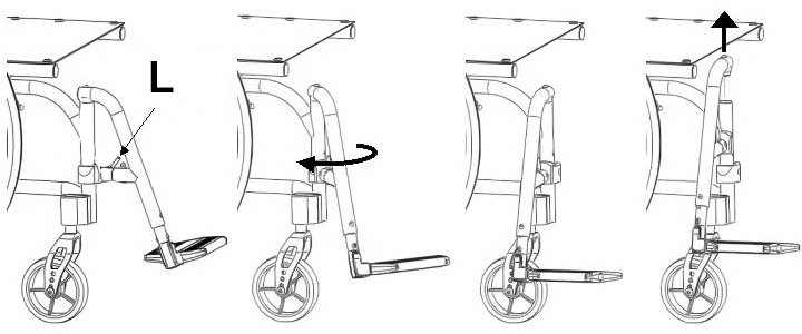
To extract the footrest:
-
Press the lever L and rotate the footrest outwards (while maintaining the lever pressed)
-
Remove the footrest from the hinge pin by pulling it upwards
|
|
The detachable footrest can be rotated both inwards and outwards, by using the same mechanism |
5.11.1. Footplate cover
For certain configurations, the wheelchair can be provided of a metal single plate that covers the plastic/aluminium footplates. The plate anchors to the footplates with light pressure, with no special locking mechanisms. To remove it, simply lift it up; to reinsert it, it must be placed over the footplates by applying slight pressure.
|
|


5.12. Accessories check
Some accessories required when setting up the wheelchair may be supplied separately. You must assemble them and check their operation before you start using the wheelchair.
6. Accessories
OFFCARR products can be configured with different accessories, described in the following paragraphs.
6.1. Armrests
OFFCARR wheelchairs can be equipped (with some limitations) with:
-
open Desk armrest (to be used with side-guards fixed to the frame)
-
closed Desk armrest (with built in side-guards)
-
closed Height adjustable Desk armrest
-
open Sport armrest (to be used with side-guards fixed to the frame)
-
closed Sport armrest (with built in side-guards)
-
closed Height adjustable Sport armrest
-
open U armrest (to be used with side-guards fixed to the frame)
-
closed U armrest (with built in side-guards)
-
closed Height adjustable U armrest
-
tip-up height adjustable L armrest (to be used with side-guards fixed to the frame)
|
|
|
Desk, open armrest |
Sport, open armrest |
U Type, open armrest |
|
|
|
Desk, closed armrest |
Sport, closed armrest |
U Type, closed armrest |
|
|
|
Desk, height adjustable armrest |
Sport, height adjustable armrest |
U Type, height adjustable armrest |
L Type, tip-up and height adjustable armrest |
||
|
|
|
Open or closed armrests (not height-adjustable) are available in two heights: 22 or 27 cm |
|
|
All armrests are supplied in a tip-up and removable version. Conflicts caused by particular configurations may affect the choice of armrests. It is anyways always possible to disable armrest tilting. |
|
|
The armrests are not designed to lift the wheelchair, either with or without a user. |
6.1.1. Tip-up armrest
According to configuration limitations, Desk, Sport and U model armrests can all be folded down.
To flip the armrests over:
|
|
|
6.1.2. Detachable armrest
Desk, Sport and U armrests are always detachable.
To remove the armrests:
|
|
|


|
|
When reinserting the armrest on the rear support, make sure that the pin C is fully inserted on its guide. This guide prevents the armrest once opened from rotating sideways when it is not locked at the front. |
6.1.3. Height adjustable armrest
Desk, Sport and U armrests are also available with height adjustable elbow-rest.
To raise/lower the elbow-rest:
|
|
|


6.1.4. Armrest Integrated in the side-guard
Depending on the selected configuration, the side-guard can incorporate the adjustable armrest.
To raise/lower the armrest:
|
|
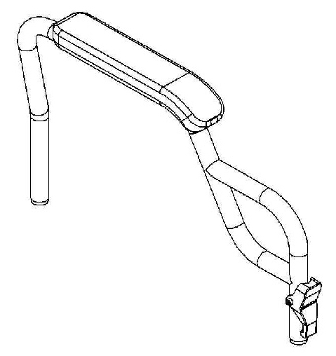
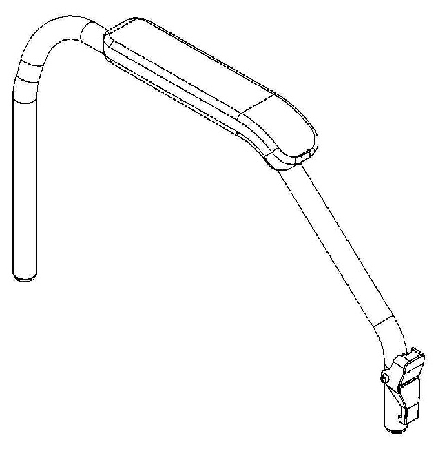
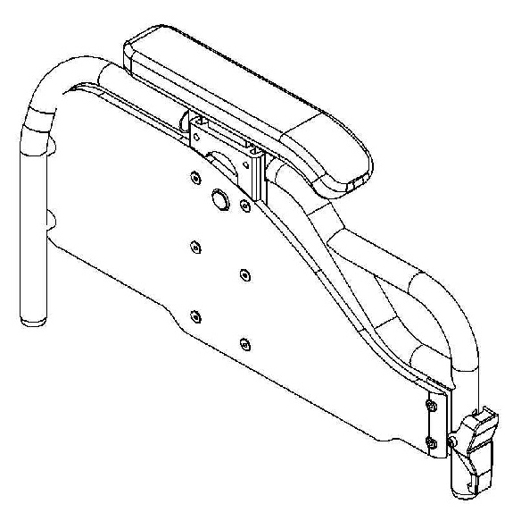
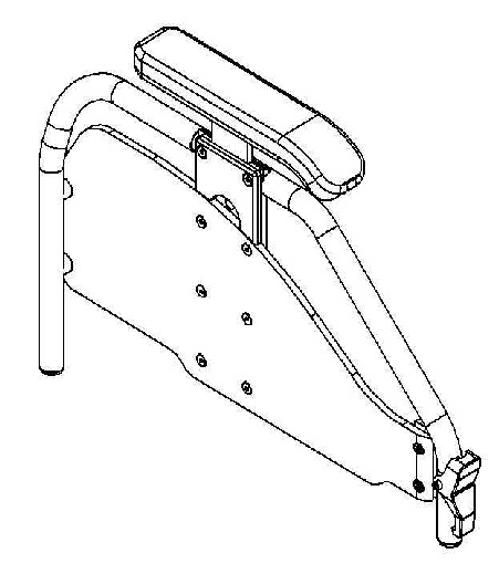
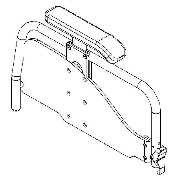
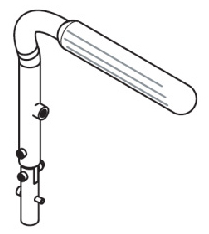
6.1.5. L type armrest, tip-up and height adjustable
Unless specifically requested, the standard height of the armrest from the seat is 220 mm. However, it is also possible to increase or decrease it by 20 or 40 mm after the order has been placed.
To adjust the height of an L type armrest:
|
|
If provided by the selected configuration, it is possible to tilt the armrest backwards and extract it. |
|
6.2. Anti-tip device
OFFCARR wheelchairs can be equipped with left and/or right anti-tip devices.
|
|
Never use the anti-tip devices as transit wheels. It is not their intended purpose. |
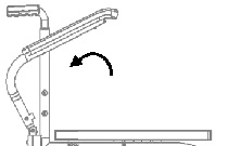
6.2.1. Use of the revolving anti-tip device
When not in use the anti-tip device is positioned horizontally under the frame:
|
|


To activate the anti-tipping device, push the knob down to unlock it and rotate it to the working position.
Always make sure that the locking position is reached after each activation or deactivation operation.
|
|
The anti-tip can be opened and closed only with the wheelchair fully opened. |
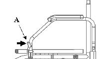
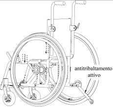
6.2.2. Fixed anti-tip device on straight rear frames
On frames with a straight rear the anti-tip device can be isolated or connected to narrow passage wheels as shown.

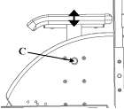
Activation of the anti-tip device
The anti-tip device is active when locked in the extended position with the AR-wheel facing downwards.
Press button A and engage the anti-tip on the anti-tip holder until pin B clicks into reference hole C.

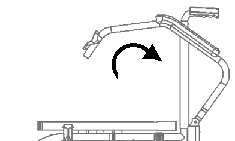
Anti-tip deactivation
-
press button A
-
rotate the telescopic tube until the small wheel is horizontal and slide it deep into a convenient position.
-
position the wheel upwards; although not essential, it is recommended to look for one of the two locking positions

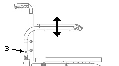
Removing anti-tip
-
press button A
-
while holding down, pull out the telescopic tube

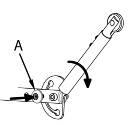
6.2.3. Using the CHILDREN3000 Anti-Tipping Device
To activate the anti-tipping device, press knob A and rotate the anti-tipping device downward into the usage position. Ensure the lock is engaged by adjusting the anti-tipping device up or down until you feel it lock in place.
|
|
6.3. Single drive
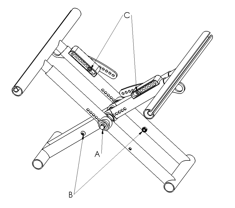
The wheelchair could be configured with a single-sided double-pushing pushrim. The single-sided double pushrim system consists of a wheel that, in addition to having the normal pushing pushrim, has a second one with a smaller diameter; this second pushrim, via a connecting axle, transmits the rotational motion to the opposite wheel without the pushing rings. The single drive option is also applicable in after-market situations by replacing the rear wheel support plates with plates suitable for the new application.
Inserting the wheel connection axle:
-
open the wheelchair
-
ensure that the wheels are properly fitted to the plates (see 5.8, “Rear wheels release and re-engagement check”)
-
sit the user in the wheelchair
-
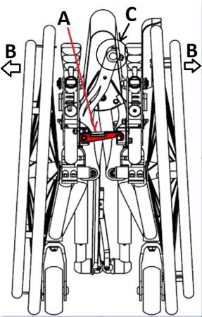
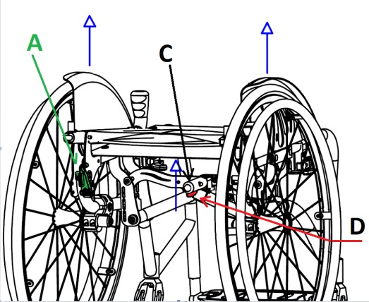
insert the connecting axle A on the rear wheel axle pins W, making sure that the coupling of the toothed ends is complete
-
move the wheelchair back and forth a few centimetres to allow for any settling
-
secure the axle locking wing screw B
|
|
Before fixing the locking wing screw, it is recommended that, with the user seated in the wheelchair, a small movement of the wheelchair is carried out to allow for any settling in width and to reduce any play on the couplings between the connecting axle and the rear wheel studs. Single-wheel hubs have pins with a toothed end for precise connection to the connecting axle. |
|
|


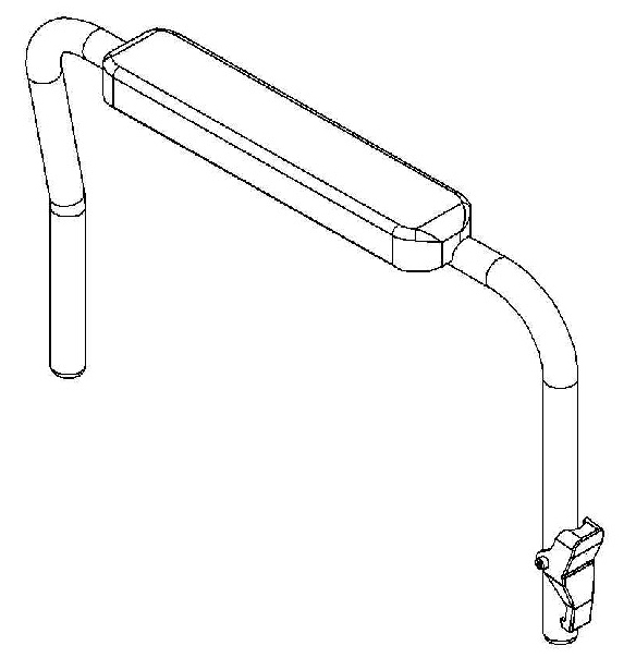
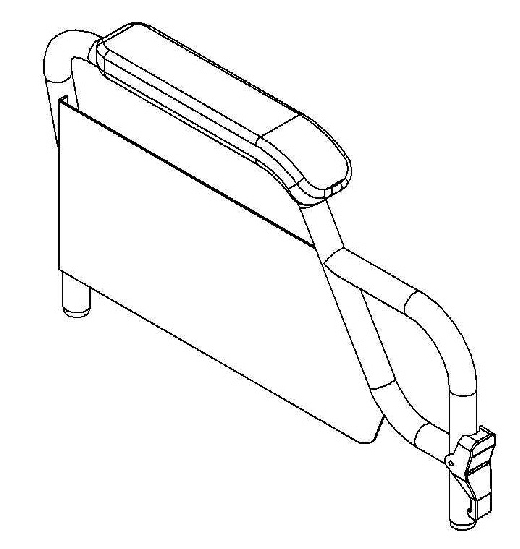
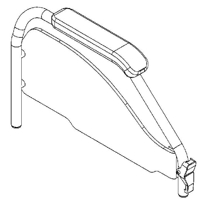
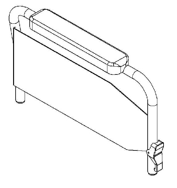
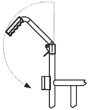
6.4. Hinged backrest
The only purpose of the articulated backrest is to reduce the height of the wheelchair for easier transport. The mounting height of the joints may vary depending on the configuration choices of the device. The joints on the backrest maintain the height adjustment feature of the backrest itself (see 14.18, “Backrest height adjustment, pushing handles adjustment”) |
|
Hinged backrest cannot be assembled with lateral supports nor stretch bar.
|
|
If the wheelchair is used with a stair lift, any hooks must rest on the fixed part of the backrest under the joint and must not under any circumstances rest on the articulated upper part of the backrest. |
|
|
It is recommended to ensure that the backrest is properly latched when climbing steps or ascending/descending even slight inclines. |
6.5. Lever-activated small wheels for narrow passages
Lever-operated narrow passage small wheels are devices that make it easier to lift the wheelchair so that the rear wheels can be pulled out and the width of the wheelchair reduced. They can be activated by the attendant, and in some cases also by the user himself. Once the narrow lever passages have been activated, make sure that the locking knob is properly engaged in its seat. To deactivate the wheels, pull the knob upwards so that it disengages from its seat and then pull the lever down. |
|

This device has some configuration limitations mainly related to the rear height of the seat from the ground and the size of the push wheels.
|
|
Lever push wheels are incompatible with some chassis and rear wheel configurations. |
|
|
Lever-mounted narrow passage wheels are incompatible with any imbalance pedals and anti-tip devices. |
|
|
Lever-mounted narrow passage wheels are always incompatible with wheelchairs configured with a curved rear. |
6.6. Tip assist pedal
The tip assist pedal is a useful device to aid an attendant when overcoming small steps or to facilitate movement over uneven terrain, gravel and cobblestones.
6.6.1. Curved rear frame tip assist pedal:
In frames configured with a curved rear, the anti-tip pedals are independent devices connected to the frame using the same holes available for attaching the rear wheel plates. In these frames it is not possible to select both anti-tip and off-setting on the same side at the same time. |
|

6.6.2. Straight rear frame unbalancing system
In frames configured with straight rear frame, the unbalancing pedal is integrated into the wheels for narrow passages support, so in case of aftersales addition request it is necessary to replace the complete support. Under the same configurations, the unbalancing pedal is also used as a support for the anti-tip device. |
|

6.7. Extended wheel plates
Extended wheel base plates for the push wheels are designed to retract the rear wheel axle and thus increase the stability of the wheelchair under certain conditions. The retraction of the push wheel axle shifts the centre of gravity of the user and wheelchair complex forward, making the wheelchair more secure. At the same time, it makes it less agile to drive and somewhat more difficult to push and manoeuvre, both for the user and the attendant. |
|

6.8. Stretch bar
The stretch bar is a device applied to the backrest with the purpose of stabilising the geometry of the wheelchair in certain configurations. It is recommended when the height of the backrest exceeds 410 mm and becomes mandatory for certain combinations of wheelchair width and backrest height, and indispensable for configurations with reclining backrest or with absorbing springs.
|
|
Any technical incompatibilities due to the presence or absence of the stretch bar require revision or cancellation of the requested configuration. |
|
|
The stretch bar must be disengaged when closing the wheelchair. |
UNRESTRAINED STRETCH BAR |
STRETCH BAR WITH CLAMPS |
|
|


6.9. Elevating footrest
Removable and elevating footplates are available for the various OFFCARR versions.
|
|
For safety reasons, the elevating footplate must only be operated by the attendant. |
|
|
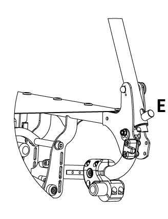
For safety reasons, the operation to return the footplate from elevated to rest must be carried out by the attendant by simultaneously operating the movement activation lever A with one hand and with the other hand accompanying the descent of the footplate. |
|
|


|
|
The footrest can be elevated to create a continuous plane with the seat: this position is unnatural for a user, so only use it if actually necessary. |
|
|
Elevating footrests are always removable and when inserted increase the overall length of the frame. |
6.10. Table
The choice of a table requires the presence of armrests in the wheelchair configuration.
The tables, which all have cutouts, are available in different materials and sizes:
Plastic (grey): |
one size, 600 mm width |
Soft padded: |
S size, 500 mm width M size, 600 mm width L size, 700 mm width |
Transparent polycarbonate table: |
S size, 500 mm width M size, 600 mm width L size, 700 mm width |
|
|
The connections between table and armrest vary depending on the model of the table itself, and the type of armrests. |
|
|
For each type of table, both central single and double attachments are available. The single attachment is not recommended in the presence of height-adjustable armrests. |
|
|
When ordering any spare parts, it is necessary to specify the serial number of the wheelchair you wish to work on, or provide the wheelchair model, and the type of armrests, elbow-rest and table used. |
Table support
|
Table support with single centre attachment
|
Polycarbonate table with double attachment
|
Polycarbonate or plastic table with double attachment
|


6.11. Swing away lateral supports
OFFCARR wheelchairs can be equipped with swing-away lateral supports.
The clamp that attaches to the backrest tube can be rotated to adjust lateral position and angle of containment. The padded support can also be independently adjusted in depth.
The padded supports are available in 4 sizes.
To unlock and open the support, simply lift it vertically by 10mm and rotate it outwards. To activate, turn the holder towards the user until it snaps into the lock when the preset position is reached. |
|

6.12. Headrest
Different kind of headrest are available:
Shaped foam headrest |
Form-fitting headrest |
Lateral supports headrest |
|
|
|


|
Adjustment of universal headrest attachment:
|

All headrests can be removed from the wheelchair by pulling them upwards.
It is possible to equip the support with a locking mechanism, this works exactly like the quick-release axle. To release it, press the button (or buttons in case of a double lock) before pulling the whole support upwards.
6.13. Pelvic band installation
OFFCARR wheelchairs are designed to accommodate the installation of a pelvic band when necessary.
The 45° pelvic strap is an accessory that can be selected at the time of ordering or added later.
To install a pelvic band, wrap it around the frame passing between the backrest and the side-guard as shown in the picture 1, and connect its two flaps inferiorly through the provided velcroed areas highlighted in picture 2.
|
|
Picture 1: View of the installed pelvic band |
Picture 2: Wrap the pelvic band around the tube as in the picture |


6.14. Spokes guards
Spokes guards on the rear wheels serve as an esthetic feature as well as protection against accidental insertion of the user’s fingers or hands between the spokes of the wheels. They can be attached to the spokes with velcro or clips depending on the specific model.
|

7. Attachment of the wheelchair for use within a motor vehicle
Where clearly indicated, the wheelchair models successfully passed the crash test according to the specifications of ISO 7176-19:2008 and can therefore be used safely in motor vehicles.
|
|
Some configurations, while available on order form, can prevent the wheelchair from being vehicle-compatible. Contact OFFCARR for further information. |
|
|
It is mandatory that all of the approved wheelchair components are installed by authorized personnel following the correct technical specifications. |
|
|
Whenever feasible, it is recommended to use the vehicle seat and its manufacturer-installed restraint systems, storing the wheelchair in the vehicle’s cargo area or securing it in the passenger area. |
|
|
When transporting an occupant the wheelchair must always face forward and be securely anchored to the vehicle. |
|
|
The wheelchair has been tested only in a forward-facing orientation with the anthropomorphic test device (ATD) restrained by both pelvic and shoulder belts. |
|
|
In order to safely transport a wheelchair user in a vehicle, the vehicle must be provided with a Wheelchair Tie-down and Occupant Restraint System (WTORS) conforming to ISO 10542 or SAE J2249 standards, appropriately installed according to the manufacturer specifications. |
|
|
Both diagonal and lap belts must be used during transport to reduce the possibility, in the event of an accident, of impacts with other components inside the vehicle. |
|
|
Anchor the wheelchair with extreme care and follow the instructions given by the manufacturer or authorized installer of the anchoring system closely. When in doubt, consult the instructions for use or contact the installer of such system. |
|
|
Never transport an occupant sitting on a wheelchair unless the device is certified according to the requirements in ISO 7176-19:2008. |
|
|
Wheelchair-mounted trays, if installed, should be removed and secured separately in the vehicle. |
|
|
When possible, other auxiliary equipment must be either secured to the wheelchair or removed and secured in the vehicle. |
|
|
Postural systems, if installed, should not be relied on for occupant restraint in a motor vehicle, unless labelled as being compliant with ISO 7176-19:2008. |
|
|
In order to securely connext the wheelchair to a vehicle, all the anchoring points must be used. |
The anchoring points are indicated by the following label (according to ISO 7176-19 specifications) |
|
|
|
If the user is transported while sitting on the wheelchair, they must be wearing a seat belt. Any safety belts for vehicle transport must be installed by authorized vehicle conversion companies and must be serviced. |
|
Belt restraints should make full contact with the shoulder, chest and pelvis, and pelvic belts should be positioned low on the pelvis near the thigh-abdominal junction (as shown on the drawing). |

|
Belt restraints must not be held away from the body by wheelchair components such as armrests or wheels (as shown on the drawing). |

|
The pelvic belt restraint should be worn low across the front of the pelvis, so that the angle of the pelvic belt restraint is within the preferred zone of 30° to 75° to the horizontal (as shown on the drawing). |

|
|
If possible, it is recommended to use the restraints with a steeper angle of 45° to 75° from the horizontal (as shown on the drawing). |
|
|
Belt restraints should be as tight as possible, consistently with user comfort, and should not be twisted during use. |
|
|
Following involvement in any type of collision, the wheelchair must be inspected by an OFFCARR representative before any further use. |
|
|
No alterations or substitutions can be made to the wheelchair securement points or to structural and frame parts or components without consulting OFFCARR. |
|
|
When applying the occupant restraint, make sure to position the seatbelt buckle so that the release button is not in contact with the wheelchair components during transport or in case of a crash. |
7.1. Vehicle attachment points
7.2. Attachment of the wheelchair for use within a motor vehicle: DIVA
|
DIVA is provided with four (4) attachment points A for a standard 4-point floor tiedown system, as indicated in the figure. When connecting the wheelchair to a vehicle, connect the attachment system to the four marked connection points. These are the most solid points of contact on the wheelchair, and the only connection points certified by the crash test. |
7.3. Attachment of the wheelchair for use within a motor vehicle: CHILDREN3000
|
CHILDREN3000 is equipped with four (4) attachment points A for a standard 4-point floor anchoring system, as shown in the diagram. When connecting the wheelchair to a vehicle, attach the fastening system to the four designated connection points marked with the appropriate symbol. These are the sturdiest contact points of the wheelchair and the only ones certified by crash testing. |
8. Maintenance, inspections and controls
Weekly:
-
✓ Check the tyre pressure. Each tyre shows on the lateral bands the maximum pressure for which they are designed. A flat tyre affects the efficiency of brakes and the agility of the wheelchair.
-
✓ Check the efficiency of the quick-release axle (see 5.8, “Rear wheels release and re-engagement check”) and if necessary proceed with the lubrication of axle and bushes.
-
✓ Check the tension of the backrest upholstery to maintain a comfortable position.
Quarterly:
-
✓ Check the tightness of all the devices' screws.
-
✓ Check the perpendicularity of the front fork support screws.
-
✓ Check the wear of the front wheels. Solid wheels might be worn to the point of affecting the overall wheelchair front setup. In this case adjust the front fork assembly or replace the wheels (see 8.2, “Replacing front wheels”).
-
✓ Check the efficiency of the bearings. Replace any stuck bearings if necessary (see 8.3, “Replacing rear wheel bearings”, 8.4, “Replacing front wheel bearings” and 8.5, “Replacing front fork holder bearings”).
-
✓ Check the efficiency of the brakes and, in case, adjust them. If the knurled pin has to be replaced, consult authorised personnel.
-
✓ Lubricate moving parts such as hinges, bearings and quick-release axles. It is suggested to use silicon oil, which is efficient and doesn’t smear.
|
|
Only choose original parts when purchasing accessories or spare parts. Contact OFFCARR if you can’t find original spare parts on the market elsewhere. |
|
|
It is recommended to refer only to authorized and qualified personnel to perform maintenance programs, adjustments, and to replace components or accessories. |
8.1. Replacement of tyre and inner tube
8.1.1. Removing the tyre and inner tube
|
|
|
|
|
|
|
|


8.1.2. Assembling the inner tube and tyre
|
|

8.2. Replacing front wheels
If necessary, the front wheels can be replaced:
|
|

|
|
It is important to select the same position for both wheels. Asymmetrical positions produce instability. |
|
|
Once the front wheel has been changed, it is essential to check or adjust the fork perpendicularity to the ground. |
8.3. Replacing rear wheel bearings
Disassembly
|

|
Assembly
|
8.4. Replacing front wheel bearings
Disassembly
|

|
Assembly
|
8.5. Replacing front fork holder bearings
Disassembly
|

|
Assembly
|
Disassembly
|

|
Assembly
|
8.6. Quick extraction devices
8.6.1. Check
The quick extraction axles are shipped already checked and adjusted. However, it is recommended to periodically verify the effectiveness of their operation.
|
|
8.6.2. Adjustment
If necessary, it is possible to adjust the axle to eliminate any play between the wheel and the frame or to complete the release of the button once the wheel is inserted. |
|

-
If the quick-release button is not completely relaxed when the wheel is inserted in the frame, it is necessary to extend the useful length of the L axle by partially unscrewing the Y nut.
-
If once the wheel has been inserted into the frame, there is play between the frame and the wheel itself, it is necessary to reduce the useful length of the L axis by partially tightening the Y nut.
|
|
The Y nut thread has a pitch of 1 mm, therefore the unscrewing or screwing of one turn involves the elongation or reduction of 1 mm. In case of adjustment, it is advisable to proceed with successive adjustments of ¼ of a turn at a time. |
9. Cleaning instruction
|
|
Cleaning and disinfection procedure have to be performed exclusively by qualified personnel. |
|
|
Follow the instructions on this manual to perform the cleaning and disinfection procedure. |
|
|
Use appropriate eye/facial protection and protective gloves, during cleaning and disinfection procedure. |
In case of contamination with blood or other body fluids, the device has to be cleaned first and then disinfected as follows:
|
|
Most of the time is convenient and more effective to remove the upholstery from the frame before to proceed with the cleaning and disinfection of either frame or upholstery. |
FRAME
-
Wash the device with lukewarm water and neutral detergent using a damp cloth to remove gross soiling
-
Remove eventual detergent residuals only with lukewarm water
-
Dry the device prior to further processing
-
Visually inspect the cleanliness of the complete device
-
Disinfect the device using 70-90% alcohol
-
Be sure it is completely dry before proceeding with use
UPHOLSTERY
In case of the user remaining the same before and after the cleaning treatment:
-
Wash, rinse, dry and disinfect the upholstery using the same process used for the frame
-
Be sure the upholstery parts are completely dry before reassembling them
In case of different user after the cleaning treatment:
-
The best course of action is to change the upholsteries with a new set
|
|
During the cleaning process the device should be also carefully inspected for damage, oxidation and faults in function. If any damage or faults are found, the involved components should be removed for service, repair or replacement. |
|
|
All waste materials related to this process must be disposed in compliance with specific local applicable law. |
10. Technical service
For any service request, please contact OFFCARR supplying the following indications:
-
Model
-
Serial number
-
Fault description
-
Any reference or order number, if available, recorded on the order form.
-
Dealer
Every component of the device is available as spare part.
11. Warranty terms
It is strongly advised to register the product on the website www.offcarr.com after delivery.
-
The device’s frame is guaranteed for 3 (three) years from the delivery date.
-
The label showing the serial number, the manufacturer address and the CE symbol cannot be removed for any reason to preserve the warranty validity.
-
Parts subject to normal wear and tear are not covered by the warranty, unless specific wear is caused by evident manufacturing fault.
-
During the warranty period OFFCARR may proceed at its own discretion to change or to repair the faulty parts.
-
The warranty does not cover damage due to negligence, carelessness, misuse or by incorrect maintenance performed by non authorized personnel.
-
If any damage occurred during transport, the forwarder company is the only responsible. It is important to inform immediately both the forwarder company and, for information, OFFCARR.
-
The warranty does not cover injury or any other damage to people or goods connected to the device’s malfunctioning.
12. Packaging, shipment and delivery
All OFFCARR products are shipped in closed cardboard cases to protect them from bumps and dust.
The package includes the device configured according with the order form, this Instruction manual and a tool kit.
The device must be transported in trucks that protect it from atmospheric agents, as shown on the packaging box.
Upon receipt, check the box integrity: open the package, remove the device and check it for damages. In case of problems, note your remark on the waybill and immediately notify both the forwarder and, for information, OFFCARR.
Once these checks, mandatory to ensure the validity of the warranty, have been carried out, place again the device in its packing until it is used and store in a cool and dry place (between - 15 and + 50 °C and with a relative humidity lower than 80 %).
Do not place any objects over the packaging box.
The packaging materials follow the European directive 94/62/EC[13].
13. Correct disposal and recycling
OFFCARR products are made of aluminium alloy (Al 7020, Al 6082, Al 2017, Al 6061, Al 5754), titanium, steel, stainless steel, carbon fibre, polyurethane, epoxy resins, other composite materials.
Recycle or disposal of all materials must be in compliance with the local applicable laws.
Contact your dealer in case of doubt or for help when disposing the device.
14. Adjustments
The wheelchair is shipped to the customer in the setup chosen on the order form.
Considering potential setup restrictions it is still possible to perform other adjustment to hone in the wheelchair to the specific user.
|
|
Please refer to authorized and qualified personnel to perform the adjustments described in this manual. |
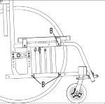
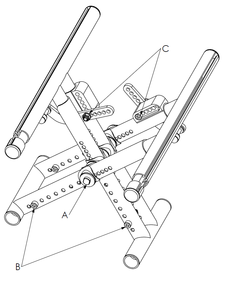
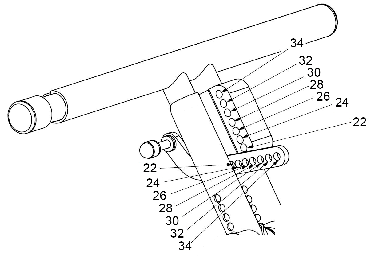
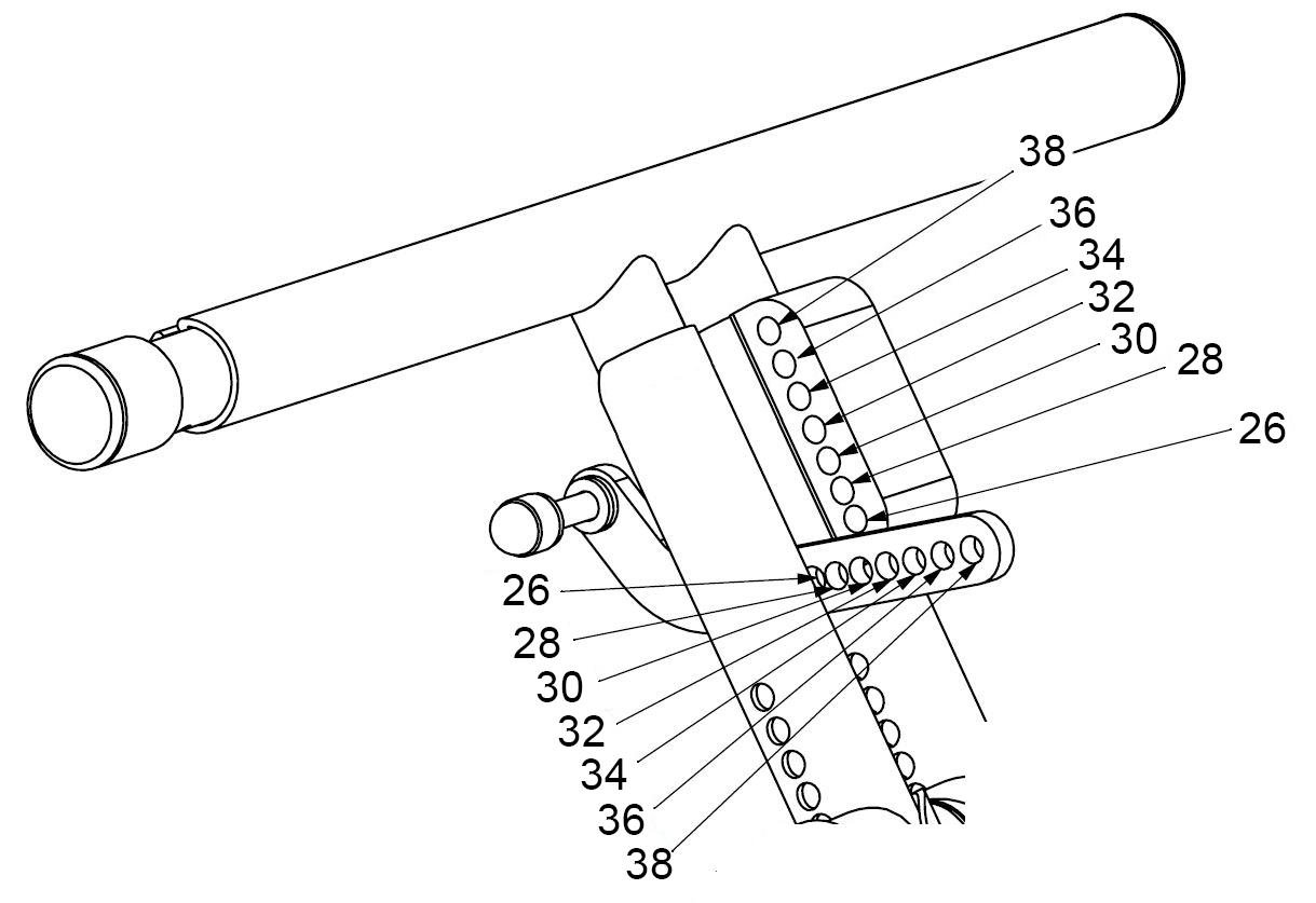
14.1. Seat Depth Adjustment (CHILDREN 3000, CHILDREN3000 PLUS, VEGA3000)
The frame of the CHILDREN, CHILDREN3000 wheelchairs is adjustable in depth by 30 mm increments, VEGA3000 frame is adjustable in depth by 20 mm increments. The maximum adjustment is 60 mm.
The extension is achieved through a pre-drilled telescopic tube that connects the front frame, crossbar, and rear frame.
14.1.1. Lenghtening of the Frame
|
|
|
|
Once the depth is adjusted, it’s necessary to adjust the brake position (see 14.12, “Brakes adjustment”) |
14.2. Width Adjustment (CHILDREN 3000 PLUS)
The crossbar of the model Children 3000 Plus wheelchairs allows for increasing the width of the wheelchair to accommodate the child’s growth. This is made possible through telescopic tubes that form the crossbar.
To adjust the width:
|
|
|
Screw holes A and B for Children 3000 plus adjustable width from 22 to 24 |

|
Screw holes A and B for Children 3000 plus adjustable width from 26 to 34 |

|
Screw holes A and B for Children 3000 plus adjustable width from 26 to 38 |

|
Screw holes C for Children 3000 plus adjustable width from 22 to 34 |
|
Screw holes C for Children 3000 plus adjustable width from 26 to 38 |
14.3. Width adjustment (VEGA3000)
VEGA3000 allows for an increase in width by adjusting the crossbar of the wheelchair. This adjustment is possible thanks to the telescopic tubes that make up the crossbar.
To adjust the width:
|
|
|
|
|


-
Using the following diagram, choose the corresponding holes on the crossbar block and the crossbar itself for the desired width.
-
Re-insert the crossbar screws C.
|
|
|


14.4. Seat Length Adjustment
|
|

14.5. Front Seat Cover Length Adjustment
|
|
Lengthening the seat cover can only be done after extending the crossbar (see 14.4, “Seat Length Adjustment”). |
The seat cover consists of a front and a rear section, held together by a velcro area.
|
|

14.6. Rear seat height adjustment
|
|

14.7. Gravity centre (COG) adjustment
The choice of the centre of gravity is always a compromise between agility and safety. With a very active configuration, the wheelchair is very agile in pushing but requires greater skill in control. A more cautious centre of gravity increases the stability of the device at the expense of its agility.
It is an individual choice linked to the general configuration of the device, the anatomy and disability of the user, and the usage environment; a choice that determines the experience of pushing and inevitably influences daily activities.
The opportunity to vary this parameter over time allows the device to accompany the user’s motor development, optimizing their potential.
|
|
Consider that the further forward the hub is mounted, the more agile the wheelchair, while the further rearward the hub is mounted, the less active the set-up is to the benefit of safety; advancing the rear wheel with respect to the backrest axis, minimises the pushing effort and gives greater agility and smoothness to the wheelchair but reduces its safety margins against backward imbalance. |
|
|
The advancement of the rear wheel in relation to the axis of the backrest minimises the pushing effort and gives the wheelchair greater agility and smoothness, but reduces its safety margins against backward imbalance, particularly on climbs. |
|
|
If the distance between the hub centre and the projection of the backrest is reduced, the wheelchair is less active but assumes a more cautious stance. |
|
|
Make sure you have chosen the same position for the wheel bushes on both sides of the frame. Asymmetrical combinations produce instability. |
|
|

14.7.1. COG adjustment: QPX
All QPX wheelchairs are supplied with adjustable axle
To adjust the axle:
|
|
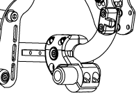
14.7.2. Gravity centre (COG) and/or rear seat height adjustment - Fixed rear plate frame (VEGA)
|
|
|


14.7.3. Gravity centre (COG) and/or rear seat height adjustment (HALLEY)
Acting on the AwP is possible to change the height and seat rear set-up.
|
|
The further the rear wheels axles are assembled, the more active and agile the wheelchair becomes, but at the same time the stability is reduced. The more back the rear wheel axles are assembled, the more stable the wheelchair is, but more effort is required to push it. |
|
|
|
|
|
|


|
|
Consider that the further the hub is connected, the more agile the wheelchair is, and the further back it is assembled, the less active but the safest the wheelchair becomes |
-
connect the wheels back to the frame checking the correct assembly (see 5.8, “Rear wheels release and re-engagement check”)
-
the operations always have to be performed symmetrically either left and right side.
|
|
Be sure to choose the same position in both wheel bushes on the back of the frame. Asymmetrical combinations produce instability. |
|
|
Once the position of the back wheel changes, it is essential to adjust the front fork perpendicularity (see 14.11, “Front fork support plate perpendicularity adjustment”) and the positioning of the parking brakes (see 14.12, “Brakes adjustment”) and, if necessary, of the side-guards (see 14.13, “Side-guard adjustment”). |
14.8. Rear wheels camber adjustment
The camber is supplied as requested in the order form. However, it is possible to change it later by replacing the rear wheel bushes:
|
|

14.9. Rear wheels camber adjustment
14.9.1. Adjusting for Non-0° Camber.
The rear wheel camber is set according to the order form selection. it is however possible to change it if required over time replacing the bush with a new with different camber
|
|
|
|
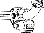


After making adjustments, tighten the nuts that secure the bushes, insert the wheels, and verify the correct insertion and locking of the quick-release axles (see 5.8, “Rear wheels release and re-engagement check”).
|
|
Once changed the front wheels it is essential to adjust the front fork perpendicularity (see 14.11, “Front fork support plate perpendicularity adjustment”). |
14.10. Front seat height adjustment
14.11. Front fork support plate perpendicularity adjustment
After making adjustments to the front height or replacing or repositioning the front wheels, the perpendicularity of the front fork plate, i.e. the perpendicularity of the fork pivot axis, must be checked and adjusted if necessary. This adjustment is necessary to achieve maximum steering feel and stability of the wheelchair.
|
|

14.11.1. VEGA
|
|
|
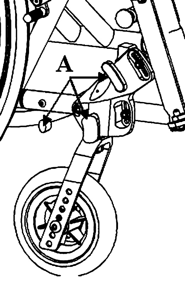
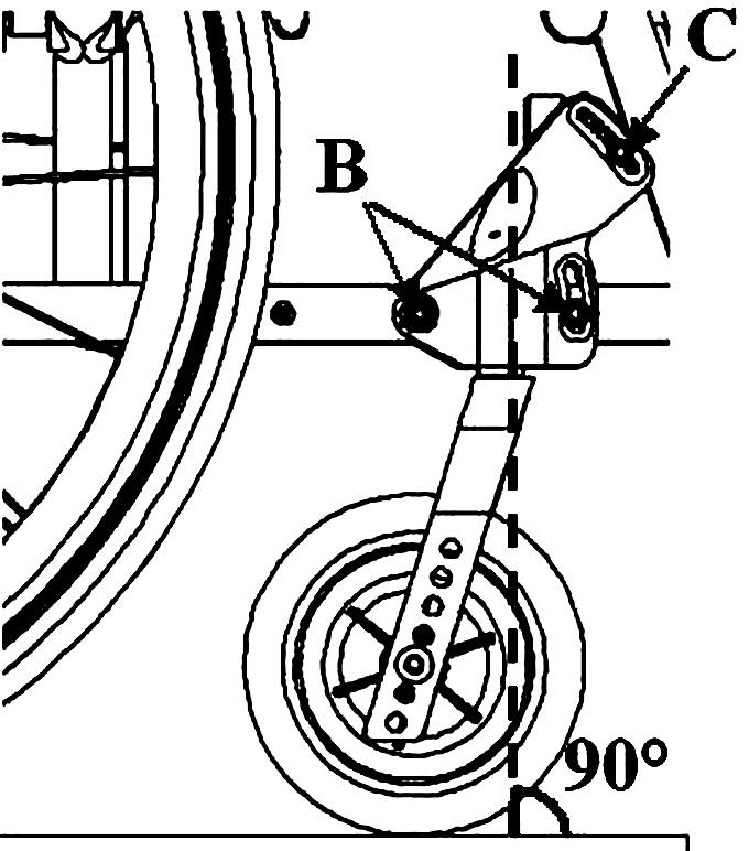
|
|
Should it prove impossible to achieve perpendicularity, it is advisable to choose the position that generates an angle immediately above 90° (as shown in the figure) in order to keep the wheelchair agile when running and changing direction. |
|
|
The adjustment must be carried out symmetrically on both forks. It is important to check the symmetry carefully after each adjustment. |
14.12. Brakes adjustment
|
|
With the exception of drum brakes, the brakes provided are only suitable for parking of the aid and not for reducing the running speed. |
If the position of the rear wheel has been changed, the position of the brakes must be adjusted accordingly. Wheelchairs can be equipped with pull, push, scissor or composite brakes.
To adjust the position of the brakes:
CLASSIC BRAKES (pull or push)
|
|

COMPOSITE AND SCISSOR BRAKES
|
|

14.13. Side-guard adjustment
Sideguards, if fitted, are attached to the wheelchair frame by means of screws which act on special slots that also allow for gradual adjustment.
In case of plastic side-guards, there is an aluminium reinforcement panel.
The side-guards are an independent accessory, are not compatible with closed armrests and are not available for reclining or dampened models.
|
|
|


14.14. Side-guard adjustment (QPX)
14.15. Backrest tilt angle adjustment
14.15.1. DIVA
The backrest tilt angle of the wheelchair is assembled according to the value specified on order form. However, depending on the configuration, the angle can be adjusted as follows:
Note: if the holes on the side-guard around the A screw cannot provide the desired tilt, it is possible to move the B screws to extend the adjustment range. |
|

14.15.2. QPX
The backrest tilt angle of the wheelchair is assembled according to the value specified on order form. However, depending on the configuration, the angle can be adjusted as follows:
|
|
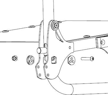
14.16. Backrest tension adjustment
The backrest tension can be easily adjusted by acting on the velcro straps:
|
|
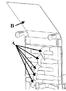
|
|
The bands A which regulate the tension of the backrest, especially the highest one, must not be so tight as to reduce the width of the wheelchair, this is to allow for easy closing and opening of the wheelchair and not to damage its movement. |
14.17. Seat upholstery adjustment and replacement
The seat tension can be adjusted through the velcro straps:
Seat tension adjustment:
|
|
|


Seat upholstery replacement:
Lay the seat upholstery on a table and bend the velcro area until the width E is 20 mm over the nominal wheelchair width;
|
|

14.18. Backrest height adjustment, pushing handles adjustment
The height of the backrest is chosen when ordering, but further adjustments are possible. The backrest has a telescopic section, regardless from the chosen pushing handles model.
|
|

-
In the presence of side-guards, remove the screws securing them to the frame and take off the corresponding support loop. Adjust the height of the backrest tube and then restore the position and fastening of the side-guards.
|
|
The same procedure can also be followed if the wheelchair has no pushing handles or is configured with height adjustable handles. |
14.19. Height adjustable pushing handles adjustment
If the wheelchair is equipped with height adjustable pushing handles it is possible to adjust them:
|
|

|
|
To change the rest position of the lever B, pull it slightly outwards to release its engagement and rotate it to the new position. |
|
|
The clamp that connects the pushing handle to the wheelchair frame can be rotated around the backrest tube. If necessary, unscrew the safety screw D before turning the screws C to loosen the clamp and allow it to rotate. Once the bracket is secured in its new position, tighten the C screws and then the D safety screw appropriately. |
14.20. Footrest height adjustment
The telescopic footrest support is inserted into the front of the frame and secured through a screw and nut couple E for each side of the frame.
|
|
For QPX It is not possible to use footplates different from the automatic closing one (such as separate or single aluminium footplates) because also in the open wheelchair position (ready for sitting) the footplate helps in its stability. |
|
|
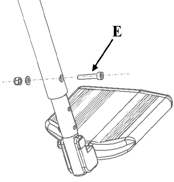
14.20.1. Seat-to-Footrest Distance Less Than 35cm (ALL)
For a seat-to-footrest distance less than 35cm, the footrest is directly fixed to the frame tube. It’s possible to adjust the footrest height using the provided holes on the frame or to move the footrest closer to or farther from the seat by rotating it around the support. |
|

Changing Footrest Height Using Frame Holes
|
|
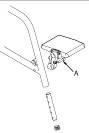
Moving the Footrest Closer to or Farther from the Seat
|
|
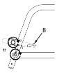
14.21. Footplate tilt adjustment
14.21.1. Single aluminium profile footplate
If the wheelchair is fitted with an aluminium profile single footplate, the orientation of the footplate can be adjusted as follows:
|
|
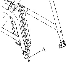
14.21.2. Separate aluminium footplates
If the wheelchair is fitted with separate aluminium profile footplates, the orientation of the footplates can be adjusted as follows:
|
|

14.21.3. Plastic footplates
If the wheelchair is fitted with plastic footplates, the orientation of the footplates can be adjusted as follows:
|
|
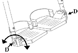
14.22. Pushrim with rivets
Replacement |
|
|

Adjust the distance between pushrim and rim
|
14.23. Pushrim with splices
Replacement |
|
|

Adjust distance between pushrim and rim |
|
|

14.24. Anti-tip device adjustment on curved rear frames
The operating height of the anti-tip device is defined during installation. However, if necessary it is possible to change its distance from the ground and thus vary the intervention threshold.
14.24.1. Ground clearance adjustment
|
|
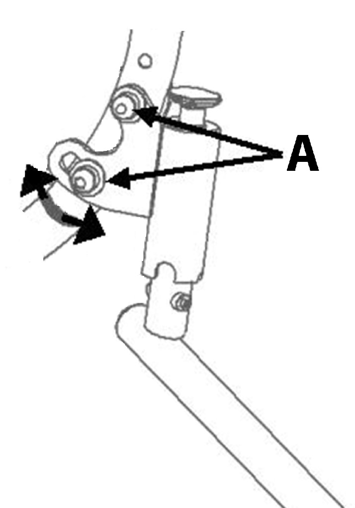
14.24.2. End terminal adjustment
|
|
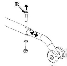
14.25. Anti-tip adjustment on straight rear frames
14.25.1. Ground clearance adjustment
The operating height of the anti-tip device is defined during installation. However, if necessary it is possible to change its distance from the ground and thus vary the intervention threshold. If the anti-tip device is fitted in combination with narrow passage wheels, any adjustment must take this into account.
|
|

14.26. CHILDREN3000 Anti-Tip Adjustment
The anti-tip intervention height is defined during assembly. However, if necessary, you can modify its distance from the ground by adjusting the position of the terminal, thus adjusting the intervention threshold.
14.26.1. Terminal Adjustment
|
|
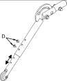
14.27. Height adjustment for lever-activated small wheels
The position of the lever-activated small wheels is defined during the assembly. However it is possible to change its distance from ground if the rear height has been changed (limited to a small range near the original height)
|
|

14.28. Table installation
To install the table on a wheelchair:
-
Loosen and remove the A screws that connect the elbow-rest to the armrest;
-
Mount the table support paying attention to its direction (right or left) and fix it using two new screws 5 mm longer than the ones removed
-
Put the table supporting tubes in place and fix them to the preferred depth with the B wing screw;
-
Fix the supports to the table with the C screws.
Table support
|
Table support with single centre attachment
|
Polycarbonate table with double attachment
|
Polycarbonate or plastic table with double attachment
|
14.29. Abductor assembly
On OFFCARR wheelchairs, a pull-out abductor can be fitted.
Follow the instructions below for fitting:
-
Mount the supplied blocks H on the side tubes of the frame
-
Loosen the screws A on the support bar without removing them
-
Assemble the support bar by inserting the lateral ends into the guides of the brackets H, paying attention to the knobs M, and fix the screws A to lock the width
-
Insert the sliding support of the abductor into its guide and secure it with the wing screw N.
To adjust the depth of the abductor, or remove it to facilitate transfers or other manoeuvres of the user in the wheelchair, act as follows:
-
Loosen the wing screw N
-
Position the dock to the desired depth and tighten the wing screw N or completely remove the abductor knob from the seat.
In this case of only removing the abductor knob, the support bar remains mounted on the wheelchair and does not allow it to be closed for transport.
To fold the wheelchair it is essential to remove the abductor knob with the support bar:
-
Pull one of the two knobs M to release the support bar;
-
Remove the support bar by pulling it out of its slots in an arching motion.
The bar can be removed with or without the knob inserted. With the user sitting in the wheelchair, it is recommended to remove the abductor knob separately and then the support bar if necessary.
Support bar
|
Scheme of the abductor parts
|


-
The distance between the seat and the abductor can be reduced by 20 mm by turning the support bar upside down.
-
The sliding support bar is available in various heights, depending on the required distance between the seat canvas and the base of the abductor knob, to suit different cushion options.
14.30. Assembly and adjustment of swing-away lateral supports
Swing-away lateral supports are accessories that can be provided at the time of ordering or can also be fitted later without special arrangements. Their fastening system allows a wide flexibility in finding the preferred positioning while always maintaining the characteristic of openness to facilitate transfers, dressing etc.
It is possible to adjust the height A, the angle between the clamp and the backrest B, the angle of the support C, and the depth position of the soft support D |
|

14.30.1. Height and width support adjustment
|
|

14.30.2. Depth position adjustment:
|
|

OFFCARR s.r.l. reserves the right to make improvements and/or changes on its products, at any time without prior notice, with respect of the device features, suitability, certifications, warranty contract and availability of spare parts according to the terms of law.